Category: Manuals

gmc sierra manual transmission

GMC Sierra Manual Transmission: A Comprehensive Guide (Updated May 5, 2026)

This guide details GMC Sierra manual transmissions, covering history, identification, common issues, maintenance, performance upgrades, and parts sourcing for enthusiasts and owners.

The Sierra, initially a trim, evolved into a successful full-size truck, facing strong market competition throughout its production run.

The GMC Sierra’s availability with a manual transmission represents a unique facet of its history, appealing to drivers who prioritize control and engagement. While increasingly rare in modern trucks, the manual Sierra offers a distinct driving experience. Historically, these transmissions were a common option, particularly in work-oriented configurations, providing durability and a direct connection to the powertrain.

However, as consumer preferences shifted towards automatics, manual transmission options became limited. Today, finding a Sierra with a manual gearbox requires searching older model years or specific, often heavy-duty, trims. This guide aims to provide a comprehensive resource for owners and enthusiasts interested in understanding, maintaining, and potentially modifying these increasingly collectible trucks. The Sierra’s journey reflects broader industry trends.

Historical Overview of Manual Sierras

Before becoming a standalone model in 1988, the GMC Sierra name designated a trim level on existing GMC trucks, often available with manual transmissions. Early Sierras frequently featured standard column-shift manual gearboxes, favored for their simplicity and cost-effectiveness. Throughout the 1990s and early 2000s, floor-shift options became more prevalent, offering improved ergonomics and driver control.

As the truck market evolved, demand for automatic transmissions grew, leading GMC to gradually reduce manual transmission availability. The Sierra continued to offer manuals in heavy-duty models for a longer period, catering to those needing robust, driver-controlled gear selection. Today, these earlier manual Sierras are gaining recognition among enthusiasts valuing a raw, connected driving experience.

Why Choose a Manual Transmission Sierra?

Opting for a GMC Sierra with a manual transmission delivers a uniquely engaging driving experience, offering greater control over gear selection and engine braking. Manual Sierras often appeal to drivers seeking a more direct connection with their vehicle, fostering a sense of involvement absent in automatics. Furthermore, manual transmissions can potentially offer improved fuel economy, though modern automatics are closing the gap.

Reliability is another draw, as manual gearboxes generally have fewer complex components than automatics, potentially reducing long-term maintenance costs. For those who enjoy driving, a manual Sierra provides a rewarding and visceral experience, making it a standout choice.

Popular Manual Transmission Options

Throughout the GMC Sierra’s history, several manual transmissions have been offered, each with its strengths. The most commonly found is the robust NV3500 5-speed, known for its durability and simplicity, frequently paired with earlier Sierra models. For heavier-duty applications, particularly in 2500HD and 3500HD Sierras, the Getrag 284 6-speed manual provided increased torque capacity and smoother shifting.

These transmissions catered to different needs, from everyday driving to demanding work tasks. Availability varied by year and model, with later Sierras seeing a significant decline in manual transmission offerings.

The NV3500 5-Speed Manual

The NV3500, a New Venture Gear transmission, became a staple in many GMC Sierra trucks, particularly from the late 1990s through the mid-2000s. Renowned for its reliability and straightforward design, it’s a favorite among those seeking a durable, driver-connected experience. It’s typically found in 1500 series Sierras and offers a relatively simple repair process.

While not known for exceptionally quick shifts, the NV3500 provides solid performance and can handle moderate torque levels. Its widespread use means parts availability is generally good, making it a practical choice for owners.

The Getrag 284 6-Speed Manual (HD Models)

The Getrag 284, a more robust 6-speed manual transmission, was primarily offered in heavy-duty (HD) GMC Sierra 2500 and 3500 models. This transmission was designed to handle the increased torque output of diesel engines and larger gasoline V8s. It provides a wider gear ratio spread, enhancing both towing capability and fuel efficiency at highway speeds.

Compared to the NV3500, the Getrag 284 offers a more refined shifting experience and greater overall strength. However, due to its complexity, repairs can be more challenging and potentially costly. Parts availability, while decent, isn’t as abundant as the NV3500.

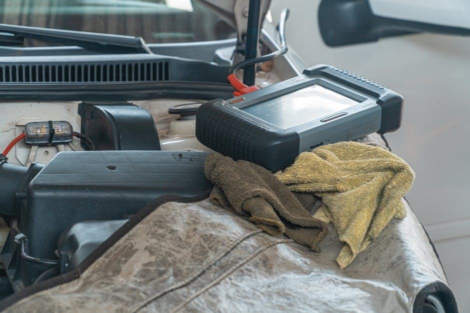
Identifying the Manual Transmission in a Sierra

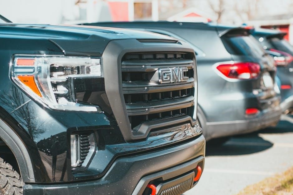
Accurately identifying your GMC Sierra’s manual transmission is crucial for parts sourcing and repair information. Two primary methods exist: decoding the Vehicle Identification Number (VIN) and visual inspection of the transmission housing. The VIN, a unique 17-digit code, contains information about the original equipment, including the transmission type.

However, VIN decoding isn’t always straightforward and may require specialized tools or databases. Visual identification involves examining the transmission case for specific markings or casting numbers. These numbers can then be cross-referenced with manufacturer documentation to determine the exact transmission model.

Decoding Sierra VINs for Transmission Information

The GMC Sierra’s Vehicle Identification Number (VIN) holds valuable clues about its original transmission. While the entire VIN provides vehicle history, specific characters indicate factory-installed options, including the transmission type. However, directly interpreting these codes can be complex, often requiring specialized VIN decoding tools or online databases.

These resources translate the alphanumeric characters into understandable information. Keep in mind that VIN decoding reveals the original transmission; modifications made by previous owners won’t be reflected. Accurate decoding is vital for ensuring correct parts selection and repair procedures, avoiding compatibility issues.

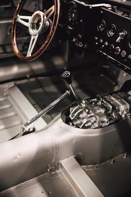
Visual Identification of Transmission Housing

Visually identifying a Sierra’s manual transmission involves examining the transmission housing itself. The NV3500 5-speed typically features a more rounded case, often with a prominent casting number visible on the side. Conversely, the Getrag 284 6-speed (found in HD models) generally has a more angular and robust housing design, reflecting its increased torque capacity.

Look for distinguishing features like the input shaft access cover and the overall size and shape. Comparing these visual cues with known images of each transmission model can aid identification. Remember that aftermarket modifications or paint can obscure original features, making accurate assessment challenging.

Common GMC Sierra Manual Transmission Problems

GMC Sierra manual transmissions, while durable, aren’t immune to issues. Clutch problems are frequent, manifesting as slippage, difficulty engaging gears, or a spongy pedal feel. Synchro issues cause grinding during shifts, particularly into specific gears, indicating worn synchronizer rings. Shift linkage wear results in sloppy or imprecise shifting, often requiring adjustment or component replacement.

Internal wear, stemming from age and mileage, can also lead to gear noise or failure. Regular maintenance and prompt attention to early symptoms are crucial for preventing more extensive and costly repairs.

Clutch Issues: Symptoms and Solutions

Common symptoms of clutch problems in a GMC Sierra include slipping (engine revs without proportional speed increase), difficulty shifting, a spongy or low pedal, and unusual noises during clutch engagement. Solutions vary based on the issue. Slippage often indicates a worn clutch disc, requiring replacement.

A low pedal might signal a hydraulic issue or cable stretch, needing bleeding or adjustment. Grinding suggests a throw-out bearing problem. Complete clutch kit replacement – disc, pressure plate, and throw-out bearing – is often the most effective long-term fix. Proper break-in is vital post-replacement.

Synchro Problems: Recognizing and Repairing

Identifying synchronizer issues in a GMC Sierra manual transmission involves noticing difficulty engaging specific gears, often accompanied by grinding noises during shifts. This typically occurs when downshifting. Worn synchros fail to match gear speeds, causing the clash. Repairing synchro problems usually requires transmission disassembly.

Individual synchro rings can sometimes be replaced, but often, complete synchro assemblies are recommended. Thorough inspection of gears for damage is crucial during this process. Professional rebuilds are common, ensuring proper clearances and lubrication. Ignoring synchro issues can lead to further transmission damage.

Shift Linkage Wear and Adjustment

Over time, the shift linkage in a GMC Sierra manual transmission can develop wear, resulting in imprecise shifting or difficulty selecting gears. Symptoms include a loose or sloppy feel in the shifter, and potentially, gears popping out of alignment. Adjustment is often the first step, ensuring proper engagement.

Inspect the linkage for worn bushings and joints; these are common failure points. Replacement of worn components is crucial for restoring accurate shifting. Proper lubrication of the linkage also helps reduce friction and wear. If adjustments don’t resolve the issue, a more in-depth inspection of the linkage components is necessary.

Maintenance for GMC Sierra Manual Transmissions

Proactive maintenance is vital for the longevity of your GMC Sierra’s manual transmission. Regular fluid checks and changes – utilizing the correct gear oil – are paramount, typically every 30,000 to 60,000 miles, depending on usage. Inspect the clutch cable for fraying or damage, replacing it if necessary to maintain smooth engagement.

Don’t neglect shift linkage lubrication; this prevents stiffness and ensures precise gear selection. Regularly check for leaks around the transmission housing. Addressing minor issues promptly prevents costly repairs down the road, keeping your Sierra shifting smoothly for years to come.

Regular Fluid Checks and Changes (Gear Oil)

Maintaining proper gear oil levels and condition is crucial for a GMC Sierra manual transmission. Check the fluid every 30,000 miles, or more frequently with heavy use. Look for discoloration or a burnt smell, indicating potential issues.

Gear oil changes should occur every 30,000 to 60,000 miles, using the manufacturer’s recommended viscosity. Proper lubrication minimizes wear on gears and synchronizers. When changing, inspect the drain plug for metal shavings, a sign of internal damage. Always dispose of used oil responsibly, following local regulations.

Clutch Cable Inspection and Replacement

For GMC Sierra manual transmissions utilizing a clutch cable, regular inspection is vital. Check the cable for fraying, kinks, or excessive slack every 30,000 miles. A worn cable can lead to inconsistent clutch engagement or complete failure.

Replacement involves disconnecting the cable at both the pedal and transmission ends. Ensure proper routing during installation to avoid binding. Adjusting the cable is crucial for correct pedal feel and full clutch disengagement. A properly adjusted cable ensures smooth shifting and prevents premature wear on clutch components.

Shift Linkage Lubrication

Maintaining the GMC Sierra’s manual transmission shift linkage is often overlooked, yet crucial for smooth operation. Regular lubrication – every 12,000 miles or annually – prevents stiffness and imprecise shifting. Use a high-quality lithium-based grease specifically designed for automotive linkages.

Apply grease to all pivot points and bushings within the linkage system. This includes where the shift lever connects to the transmission and all joints along the connecting rods. Proper lubrication reduces wear, minimizes play, and ensures crisp, accurate gear selection, enhancing the driving experience.

Performance Modifications for Manual Sierra Transmissions

Enhancing a GMC Sierra’s manual transmission performance involves several key upgrades. Upgraded clutch kits are paramount for handling increased torque from engine modifications, preventing slippage and ensuring power transfer. Short throw shifters dramatically reduce throw length, enabling quicker, more precise gear changes, improving driving engagement.

For those seeking optimized gear ratios, performance gear sets can be installed, tailoring the transmission to specific driving styles or terrains. These modifications collectively transform the driving experience, maximizing the potential of your manual Sierra, and delivering a more responsive and enjoyable ride.

Upgraded Clutch Kits for Increased Torque Capacity

When modifying a GMC Sierra for increased power, the stock clutch often becomes a limiting factor. Upgraded clutch kits address this by utilizing stronger pressure plates, more robust clutch discs, and reinforced release bearings. These components work together to withstand significantly higher torque loads.

Options range from organic clutches for street performance to ceramic or metallic clutches designed for extreme duty and racing applications. Selecting the right kit depends on your specific modifications and intended use. A properly matched clutch ensures reliable power transfer and prevents premature wear, maximizing the benefits of engine upgrades.

Short Throw Shifters for Faster Gear Changes

For enthusiasts seeking a more engaging driving experience, short throw shifters are a popular upgrade for GMC Sierra manual transmissions. These shifters reduce the distance the lever travels between gears, resulting in quicker, more precise shifts. This translates to improved performance and a sportier feel.

Available in various designs – including weighted shift knobs and adjustable linkages – short throw shifters allow drivers to customize the shift feel to their preference. Installation is typically straightforward, though some kits may require minor modifications. The benefit is a noticeably more connected and responsive driving experience, enhancing control and enjoyment.

Performance Gear Sets for Optimized Ratios

While less common than clutch or shifter upgrades, performance gear sets offer a significant, albeit complex, path to optimizing a GMC Sierra manual transmission. These sets alter the final drive ratios, impacting acceleration, top speed, and overall drivability. Careful consideration of intended use is crucial – off-road builds benefit from lower (numerically higher) ratios for increased torque, while highway-focused trucks may prefer taller ratios.

Installation requires complete transmission disassembly and specialized knowledge. Matching the gear set to tire size and engine characteristics is vital for optimal results. This modification is best left to experienced professionals, ensuring proper setup and avoiding potential damage.

Finding Parts for GMC Sierra Manual Transmissions

Sourcing parts for older GMC Sierra manual transmissions can present challenges, but several avenues exist. Online retailers specializing in truck parts, like Summit Racing or RockAuto, often carry common wear items and rebuild kits. Local auto parts stores may stock basic components, while salvage yards offer potentially cost-effective options, though condition verification is essential.

For original or specific parts, GMC dealer parts departments remain a reliable source, albeit potentially more expensive. Online forums and communities dedicated to GMC trucks can also be invaluable for locating rare or discontinued parts from fellow enthusiasts.

Online Retailers Specializing in Truck Parts

Numerous online retailers cater specifically to truck enthusiasts needing GMC Sierra manual transmission parts. Summit Racing and RockAuto are prominent examples, offering extensive catalogs with detailed parts breakdowns and competitive pricing. These platforms frequently stock clutch kits, synchronizers, gear sets, and various seals and gaskets.

Advance Auto Parts and AutoZone also carry a selection, though their inventory may be more limited for older models. Always verify part compatibility using the vehicle’s VIN before ordering, and consider shipping costs when comparing prices across different retailers.

Local Auto Parts Stores and Salvage Yards

While online retailers offer convenience, local auto parts stores like NAPA and smaller, independent shops can provide immediate access to common GMC Sierra manual transmission components. They often stock clutch cables, gear oil, and basic repair parts. However, specialized items may require ordering.

Salvage yards (also known as junkyards) represent a cost-effective option for locating used transmissions, gears, or housings. Thorough inspection is crucial to assess the condition of salvaged parts before purchase. Be prepared to spend time searching and potentially disassembling components yourself.

GMC Dealer Parts Departments

GMC dealer parts departments offer the advantage of guaranteed genuine GMC parts for your Sierra’s manual transmission. This ensures compatibility and quality, though typically at a higher price point than aftermarket or used options. They can accurately identify the correct parts based on your truck’s VIN.

Dealers are particularly useful for sourcing rare or discontinued components, and they often maintain detailed parts diagrams. While potentially more expensive, using genuine GMC parts can preserve the vehicle’s originality and potentially extend the transmission’s lifespan. Expect expert assistance and warranty coverage.

DIY vs. Professional Repair

Deciding between DIY and professional repair for your GMC Sierra’s manual transmission hinges on your mechanical skill and available tools. Simple tasks like clutch cable replacement or shift linkage lubrication are often manageable for experienced DIYers. However, complex repairs – like synchronizer replacement or transmission rebuilds – demand specialized knowledge and equipment.

Professionals offer diagnostic expertise and warranty their work. A mechanic’s cost includes labor, parts, and potential shop fees. Carefully assess your abilities and the repair’s complexity before attempting a DIY fix; improper work can lead to further damage and higher costs.

Assessing Your Mechanical Skill Level

Honest self-assessment is crucial before tackling GMC Sierra manual transmission repairs. Have you successfully completed similar automotive projects? Are you comfortable using hand tools, torque wrenches, and diagnostic equipment? Can you accurately follow repair manuals and understand technical diagrams?

Experience with drivetrain components is particularly valuable. If you’ve previously replaced clutches, rebuilt differentials, or worked with gearboxes, you’re better prepared. If your mechanical experience is limited, start with simpler maintenance tasks before attempting complex transmission work. Don’t hesitate to seek guidance from experienced mechanics or online forums.

Cost Comparison: DIY vs. Mechanic

Evaluating the financial implications of DIY versus professional repair is essential. A DIY approach saves on labor costs, often the largest expense. However, factor in the cost of specialized tools, diagnostic equipment, and potential for mistakes requiring further repair.

Professional mechanics offer expertise and warranty their work, but hourly rates can be substantial. A simple clutch replacement might cost $800-$1500 at a shop, while DIY could be $300-$600 for parts. Complex transmission rebuilds significantly favor professional expertise due to specialized knowledge and equipment, despite higher overall costs.

GMC Sierra Manual Transmission Years & Specifics

Sierra manual transmission availability varied significantly by year. 1999-2006 models commonly featured the robust NV3500 5-speed, known for its durability. The 2007-2013 generation continued with the NV3500, but saw reduced manual transmission options overall.

From 2014-2023, manual Sierras became increasingly rare, largely limited to specific HD (heavy-duty) configurations, often equipped with the Getrag 284 6-speed. Identifying the exact transmission requires VIN decoding and visual inspection, as GMC offered different gear ratios within each transmission type depending on the truck’s intended use.

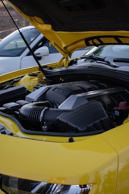
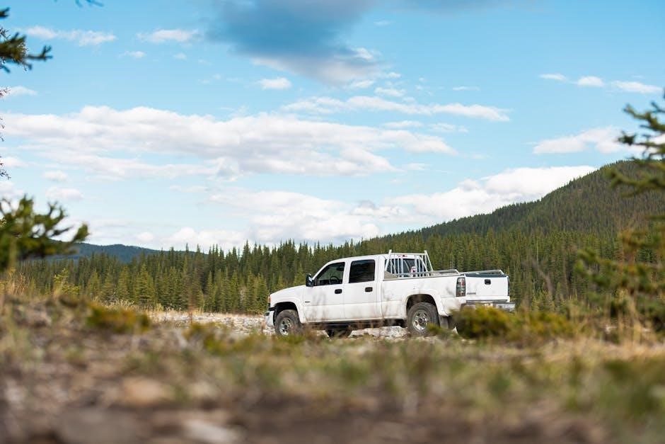
1999-2006 Sierra Manual Transmission Details

During this period, the GMC Sierra predominantly utilized the New Venture Gear NV3500 5-speed manual transmission. This gearbox proved remarkably reliable, becoming a staple for Sierra owners seeking a driver-focused experience. It was paired with various engine options, including the 4.3L V6 and 5.3L/6.0L V8s.

Common issues within this era included clutch wear, particularly with heavier use or towing. Shift linkage adjustments were occasionally needed to maintain precise gear selection. Overall, the NV3500 offered a straightforward and durable manual transmission solution for the Sierra platform.

2007-2013 Sierra Manual Transmission Details

The 2007-2013 GMC Sierra saw a shift towards reduced manual transmission availability, largely due to changing market demands. While still offered, it became increasingly rare, primarily found in base work truck configurations. The NV3500 5-speed continued as the standard option during these years, maintaining its reputation for robustness.

However, owners reported similar issues to the previous generation, including potential clutch wear and the need for occasional shift linkage adjustments. Finding replacement parts could become slightly more challenging as manual transmission models diminished in overall production volume.

2014-2023 Sierra Manual Transmission Availability (Limited)

From 2014 onward, the GMC Sierra’s manual transmission offerings became severely restricted. Demand for manual transmissions in full-size trucks plummeted, leading GMC to discontinue the option for most configurations. It was virtually nonexistent in higher trim levels, focusing solely on the most basic work truck models, if available at all.

This period marks a significant decline in manual Sierra production. Parts availability, while still present, began to dwindle, potentially increasing costs for repairs and maintenance. The NV3500 remained the sole offering during these limited years.

The Future of Manual Transmissions in the Sierra

The outlook for manual transmissions in the GMC Sierra appears bleak, mirroring industry-wide trends. Automakers are prioritizing automatic transmissions and advanced driver-assistance systems, diminishing the demand for manual options. New Sierra models are unlikely to offer a manual transmission in the foreseeable future.

However, a dedicated aftermarket community could sustain interest. Enthusiasts may continue modifying existing trucks and sourcing parts. Potential exists for specialized companies to offer updated manual transmission kits, ensuring the option remains viable for those who prefer a traditional driving experience, despite limited factory support.

Declining Availability and Market Trends

The availability of manual transmissions in the GMC Sierra has steadily decreased over the years. What was once a common option, particularly in earlier models, became increasingly rare, culminating in limited availability in recent years. This decline reflects broader market trends, with consumer preference shifting overwhelmingly towards automatic transmissions.

Factors driving this trend include the convenience of automatics, advancements in automatic transmission technology (like more gears and smoother shifting), and the increasing integration of driver-assistance features that work best with automatic systems. Consequently, manufacturers are reducing investment in manual transmission development and production.

Potential for Aftermarket Support and Revival

Despite the declining factory availability, a dedicated community of GMC Sierra enthusiasts maintains a strong interest in manual transmissions. This passion fuels a robust aftermarket for parts, upgrades, and even complete transmission conversions. Companies specializing in performance truck components continue to offer solutions for those seeking a manual driving experience.

The potential for a limited “revival” exists through these aftermarket channels, allowing owners to retrofit older manual transmissions or upgrade existing ones. While a return to factory-offered manuals seems unlikely, the aftermarket ensures that the option remains viable for those willing to invest in it, preserving a key aspect of the Sierra’s heritage.

Resources for GMC Sierra Manual Transmission Owners

Sierra owners committed to maintaining their manual transmissions have several valuable resources available. Online forums, dedicated to GMC trucks and specifically manual swaps or repairs, provide a platform for sharing knowledge, troubleshooting issues, and sourcing hard-to-find parts. These communities often feature detailed build threads and expert advice.

Furthermore, access to technical service manuals (TSMs) and detailed diagrams is crucial for accurate repairs and maintenance. These manuals, often available for purchase online or through GMC dealer parts departments, offer step-by-step instructions and specifications. Utilizing these resources empowers owners to confidently tackle repairs and preserve their Sierra’s manual driving experience.

Online Forums and Communities

Numerous online forums cater specifically to GMC Sierra enthusiasts, offering dedicated sections for manual transmission discussions. Websites like Sierra Forums and broader truck-centric platforms host threads covering everything from clutch replacements to transmission swaps. These communities are invaluable for diagnosing problems, finding solutions, and connecting with experienced owners.

Active members frequently share detailed repair logs, parts recommendations, and technical expertise. Facebook groups also provide a convenient space for quick questions and local parts sourcing. Engaging with these online communities fosters a collaborative environment, ensuring Sierra owners have access to a wealth of knowledge regarding their manual transmissions.

Technical Service Manuals and Diagrams

Accessing GMC Sierra technical service manuals (TSMs) is crucial for in-depth repair and maintenance. These manuals, often available for purchase online or through GMC dealer parts departments, provide detailed diagrams of the manual transmission components, torque specifications, and step-by-step repair procedures.

Haynes and Chilton manuals offer a more generalized approach, but may lack the specific detail found in the official TSMs. Online databases sometimes host scanned versions of these manuals, though legality should be verified. Detailed exploded views and wiring diagrams are essential for complex repairs, ensuring correct assembly and functionality of the Sierra’s manual transmission system.

stanley fatmax jump starter manual

The Stanley Fatmax jump starter offers reliable power, detailed in its instruction manual, for various vehicles․ It’s a versatile tool, often including a power station and air compressor․

Accessing the PDF manual is crucial for safe operation, covering features like the 1800A Lithium model (LJ18FC) and the J15CF with air compressor functionality․

Stanley Black & Decker provides comprehensive guides, ensuring users understand connection methods and safety precautions, as outlined in the official manuals available online․

What is a Stanley Fatmax Jump Starter?

A Stanley Fatmax jump starter is a portable device designed to provide a boost of power to vehicles with discharged batteries, detailed extensively within its accompanying manual․ These units, like the PP1DCS digital power station, offer a convenient alternative to traditional jump starting methods․

The manual emphasizes that these devices aren’t just for emergencies; many models, such as the J15CF, integrate an air compressor for tire inflation․ Stanley provides clear instructions, often available as a PDF, covering safe operation and component understanding․

Models range in amperage, with options like the 1800A LJ18FC, and the manual guides users through proper clamp connection and power-on sequences, ensuring a successful jump start․

Benefits of Owning a Stanley Fatmax Jump Starter

Owning a Stanley Fatmax jump starter, as detailed in the manual, provides peace of mind and self-sufficiency․ No longer reliant on external assistance, you can quickly address a dead battery, referencing the manual for correct procedures․

Many models, like those with integrated air compressors, offer multi-functionality, saving space and cost․ The manual highlights the USB charging capabilities, acting as a portable power bank for devices․

The manual stresses safety features, reducing the risk of damage to your vehicle’s electrical system․ Accessing the PDF version ensures you have readily available guidance for any situation․

Models Available: A Quick Overview

The Stanley Fatmax range offers diverse jump starters, each with a specific manual outlining its features․ The LJ18FC, a 1800A Lithium model, is popular for its power and portability, detailed in its accompanying manual․

The J15CF combines jump-starting with an air compressor, its manual covering both functionalities․ Digital Power Station models (PP1DCS) provide broader power solutions, explained in their respective manuals․

Older 350A models with compressors also exist, with Spanish-language manuals available․ Always consult the manual specific to your model for accurate instructions and safety guidelines․

Safety Precautions

The manual emphasizes reading instructions to reduce battery explosion risk․ Proper connection methods, detailed in the manual, are vital for safe jump-starting procedures․

General Safety Guidelines

Before utilizing your Stanley Fatmax jump starter, thoroughly review the instruction manual for critical safety information․ Always wear appropriate eye protection during jump-starting procedures to shield against potential sparks or acid spray․ Ensure the vehicle’s ignition is completely off before connecting the clamps․

Never allow the clamps to touch each other while connected to a battery, as this can cause a dangerous short circuit․ Work in a well-ventilated area, as batteries can release explosive gases․ Keep the jump starter away from flammable materials and children․ Adhering to these guidelines, as detailed in the manual, minimizes risks․

Battery Safety Information

The Stanley Fatmax jump starter manual emphasizes caution around vehicle batteries․ Batteries contain corrosive acid; avoid contact with skin, eyes, and clothing․ If contact occurs, immediately flush with water and seek medical attention․ Never smoke or introduce open flames near a battery, as it releases flammable hydrogen gas․

Ensure proper ventilation during jump-starting․ The manual warns against jump-starting a frozen battery, as it may explode․ Always disconnect accessories before jump-starting․ Regularly inspect the jump starter’s battery for damage, following the manual’s maintenance instructions․

Jump Starting Safety Procedures

The Stanley Fatmax jump starter manual stresses following vehicle-specific instructions․ Before connecting, ensure both vehicles are off and not touching․ Connect the red clamp to the positive (+) terminal and the black clamp to a grounded metal surface, away from the battery․

Power on the jump starter, then attempt to start the dead vehicle․ If it doesn’t start, check connections and wait before retrying․ Disconnect clamps in reverse order – black first, then red – as detailed in the manual․ Avoid short circuits and always wear eye protection․

Understanding the Components

The manual details key parts: clamps, a power switch with indicators, USB ports for charging, and potentially an air compressor, varying by model․

Familiarize yourself with each component’s function, as described in the Stanley Fatmax instruction guide, for optimal and safe operation․

Jump Starter Clamps (Red & Black)

The Stanley Fatmax jump starter manual emphasizes correct clamp connection․ The red clamp signifies positive polarity, connecting to the vehicle’s positive terminal․ Conversely, the black clamp represents negative polarity, attaching to a grounded metal surface—not directly to the negative battery terminal․

This grounding practice minimizes spark risk near the battery․ The manual stresses ensuring a secure grip with the clamps for effective current transfer․ Incorrect connection can damage the jump starter or vehicle’s electrical system, so always consult the vehicle’s instruction manual for specific guidance․

Power Switch and Indicator Lights

The Stanley Fatmax jump starter manual details the function of its power switch and indicator lights․ The power switch activates the unit, initiating the jump-starting or air compressor functions․ Indicator lights display the unit’s status—power on, charging, or potential errors․

The manual explains that specific light patterns indicate low battery, overload, or reverse polarity․ Understanding these signals is crucial for safe and effective operation․ Always refer to the manual for interpreting light codes before and during use, ensuring proper functionality and preventing damage․

USB Ports and Charging Capabilities

The Stanley Fatmax jump starter manual highlights its integrated USB ports, enabling charging of mobile devices․ These ports function as a portable power bank, offering convenience beyond jump-starting capabilities․ The manual specifies output amperage for optimal charging speeds․

Charging the jump starter itself can occur via AC adapter or USB․ The manual details charging indicators and estimated times for a full charge․ Utilizing the USB port for charging requires understanding the device’s power requirements, as detailed within the product documentation․

Air Compressor Functionality (If Applicable)

The Stanley Fatmax jump starter manual, for models equipped with an air compressor (like the J15CF), provides detailed instructions for its use; Connecting the air hose is the first step, ensuring a secure fit․ The manual emphasizes setting the desired tire pressure before operation, preventing over-inflation․

Operating the compressor involves understanding its PSI capabilities, as outlined in the specifications section of the manual․ Proper usage ensures efficient tire inflation and extends the lifespan of the compressor, as detailed in maintenance guidelines․

Jump Starting Procedure

The manual details connecting clamps (red to positive, black to ground), powering on the unit, and starting the vehicle, then disconnecting in reverse order․

Always consult your vehicle’s manual for specific connection points, as detailed in the Stanley Fatmax jump starter’s instructions․

Step 1: Connecting the Clamps to the Battery

According to the Stanley Fatmax jump starter manual, begin by ensuring the vehicle is turned off․ Then, carefully connect the red clamp to the positive (+) terminal of the battery, followed by the black clamp to a solid, unpainted metal surface on the vehicle’s chassis – serving as the negative (-) ground․

The manual emphasizes verifying a secure connection for both clamps, avoiding any loose contact․ Double-check polarity before proceeding, as incorrect connections can cause damage․ Refer to your vehicle’s instruction manual for specific battery access and grounding points, as detailed within the Stanley guide․

Step 2: Powering On the Jump Starter

The Stanley Fatmax jump starter manual instructs users to power on the unit after establishing secure clamp connections․ Locate the power switch, typically indicated in the manual with a clear diagram, and toggle it to the ‘ON’ position․ Observe the indicator lights; they confirm the jump starter is receiving power and ready for use․

Some models feature a safety interlock, preventing activation without proper clamp attachment․ The manual stresses waiting briefly after switching on, allowing the unit to initialize before attempting to start the vehicle, ensuring optimal performance and preventing potential issues․

Step 3: Starting the Vehicle

The Stanley Fatmax jump starter manual advises attempting to start the vehicle after the unit is powered on and clamps are securely connected․ Turn the vehicle’s ignition key to the start position, holding it for no more than 10-15 seconds, as prolonged cranking can damage the starter motor․

If the vehicle doesn’t start, consult the manual for troubleshooting․ Wait a minute before attempting another start, allowing the jump starter to recover․ Repeated failures suggest an issue beyond a simple battery discharge, requiring professional diagnosis․

Step 4: Disconnecting the Jump Starter

The Stanley Fatmax jump starter manual stresses the importance of disconnecting in the reverse order of connection․ First, turn off the jump starter․ Then, remove the black (negative) clamp from the vehicle’s chassis․ Following this, carefully detach the red (positive) clamp from the battery terminal․

Ensure the clamps don’t touch each other or any metal parts of the vehicle during removal․ Store the jump starter safely, and consult the manual for proper storage guidelines to maintain its functionality and longevity․

Air Compressor Usage (If Applicable)

The manual details connecting the air hose to the unit and setting the desired tire pressure․ Operate the compressor following the manual’s instructions carefully․

Connecting the Air Hose

The Stanley Fatmax jump starter manual provides clear instructions for securely attaching the air hose․ Locate the designated air compressor outlet on the unit, typically featuring a quick-connect fitting․ Ensure the hose is free from kinks or damage before connecting it firmly to the outlet, listening for a click to confirm a secure attachment․

Proper connection is vital for optimal air compressor performance and to prevent air leaks during tire inflation․ Always refer to the manual for specific hose compatibility and connection procedures related to your particular Stanley Fatmax model․

Setting the Tire Pressure

The Stanley Fatmax jump starter manual emphasizes determining your tire’s recommended pressure, found on the tire sidewall or vehicle doorjamb․ Do not exceed the maximum pressure indicated on the tire․ The air compressor often features a built-in pressure gauge or requires a separate gauge for accurate readings․

Input the desired pressure into the compressor’s digital display (if equipped) or use the gauge to monitor inflation․ Regularly check the pressure during inflation to avoid overfilling, consulting the manual for specific guidance․

Operating the Air Compressor

The Stanley Fatmax jump starter manual details compressor operation: connect the air hose securely to both the unit and the tire valve stem․ Ensure a tight seal to prevent air leakage, as described in the instructions․ Power on the unit and select the desired pressure or inflation mode․

Monitor the pressure gauge closely during inflation, stopping when the target pressure is reached․ The manual cautions against prolonged use to prevent overheating; allow cooling periods as needed․ Disconnect the hose after use․

Charging the Jump Starter

The manual explains charging via AC adapter or USB; indicators show status and timing․ Proper charging maintains optimal performance, as detailed in the PDF․

Using the AC Adapter

The Stanley Fatmax jump starter manual details AC adapter charging procedures․ Locate the charging port on the unit and connect the provided adapter securely․ Ensure the adapter is plugged into a functioning wall outlet․

Charging indicators will illuminate, signifying the charging process has begun․ Refer to the manual for specific indicator light meanings – solid or flashing lights denote different stages․

Allow sufficient charging time, as outlined in the manual, to fully replenish the battery․ Avoid interrupting the charging cycle prematurely to maximize battery lifespan and performance․

Charging via USB

The Stanley Fatmax jump starter manual explains USB charging capabilities for added convenience․ Locate the USB port on the unit and connect a compatible USB cable to a power source, like a computer or USB wall adapter․

USB charging is typically slower than using the AC adapter, but provides a flexible charging option․ Monitor the charging indicators, as described in the manual, to track progress․

The manual will specify if the unit can charge while powering devices via USB, and any limitations on charging speed or simultaneous operation․

Charging Indicators and Times

The Stanley Fatmax jump starter manual details specific charging indicators – typically LED lights – showing charging status: charging, full, or error․ Refer to the manual for the exact light patterns for your model․

Charging times vary significantly based on the discharge level and charging method (AC adapter vs․ USB); A fully depleted battery may take several hours to recharge using the AC adapter․

USB charging will generally require considerably longer․ The manual provides estimated charging times under different conditions, ensuring optimal battery health and performance․

Troubleshooting Common Issues

The Stanley Fatmax manual offers solutions for issues like no power, failed starts, or compressor malfunctions․ Consult it for diagnostic steps and fixes․

It details troubleshooting for USB port failures, referencing LED indicators and potential causes, ensuring optimal device functionality as per the manual․

Jump Starter Won’t Power On

If your Stanley Fatmax jump starter fails to power on, the manual advises checking the charging status first․ Ensure the unit has been adequately charged using the AC adapter or USB port․

Verify the power switch is fully engaged․ Inspect the clamps for proper connection and any visible damage․ A blown fuse, detailed in the manual’s diagrams, could also be the culprit, requiring replacement․

If these steps don’t resolve the issue, consult the troubleshooting section of the manual for further guidance or contact Stanley customer support for assistance․

Vehicle Won’t Start After Jump Attempt

If your vehicle doesn’t start after a jump attempt with the Stanley Fatmax, the manual recommends verifying correct clamp connections – red to positive, black to ground․ Ensure a solid connection, as detailed in the connection method specified in your vehicle’s instruction manual․

Allow the jump starter to charge the vehicle’s battery for a few minutes before attempting to start again․ A severely discharged or faulty battery may require professional attention, as noted in the manual’s troubleshooting section․

Check for any underlying vehicle issues preventing startup․

Air Compressor Not Working

If the air compressor on your Stanley Fatmax isn’t functioning, consult the manual for troubleshooting steps․ First, ensure the unit is powered on and the air hose is securely connected, as illustrated in the manual’s diagrams․

Verify the tire pressure setting is correct and the compressor isn’t overheating from prolonged use․ Check the manual for duty cycle limitations․ A faulty fuse or internal component may also be the cause․

If issues persist, refer to the warranty information․

USB Ports Not Charging Devices

If your Stanley Fatmax jump starter’s USB ports aren’t charging devices, first confirm the unit has sufficient charge, referencing the manual’s charging indicators․ Ensure the USB cable is functioning correctly by testing it with another device․

Check the manual for the USB port’s output amperage and ensure your device is compatible․ Some devices require higher amperage than the jump starter provides․

A blown internal fuse could also be the issue; consult the manual for fuse replacement instructions․

Maintenance and Storage

The manual advises cleaning the Stanley Fatmax jump starter regularly and storing it in a cool, dry place to prolong battery life and performance․

Cleaning the Jump Starter

The Stanley Fatmax jump starter manual emphasizes keeping the unit clean for optimal performance and longevity․ Disconnect the jump starter from any power source before cleaning․ Use a damp cloth to wipe down the exterior casing, removing any dirt or debris․

Avoid using harsh chemicals or solvents, as these can damage the plastic components․ Ensure the clamps are clean and free from corrosion; a wire brush can be used carefully for this purpose․ Allow the unit to dry completely before storing or using it again, following the manual’s guidance․

Proper Storage Conditions

The Stanley Fatmax jump starter manual recommends storing the unit in a cool, dry place, away from direct sunlight and extreme temperatures․ Avoid storing it in areas with high humidity, which can cause corrosion․ Ensure the power switch is in the ‘off’ position to prevent accidental activation during storage․

It’s best to store the jump starter on a flat surface, protecting it from physical damage․ Periodically check the battery level, as outlined in the manual, to maintain optimal readiness․ Proper storage extends the lifespan of your device․

Battery Maintenance Tips

The Stanley Fatmax jump starter manual emphasizes regular charging to maintain peak performance․ Avoid fully discharging the battery, as this can reduce its lifespan․ Charge the unit after each use, or at least every three months, even if it hasn’t been used, following the manual’s charging instructions․

Store the jump starter with a partial charge․ Extreme temperatures can affect battery performance; therefore, avoid storing it in very hot or cold environments․ Refer to the manual for specific battery type guidance and optimal charging practices․

Technical Specifications

The manual details voltage, amperage, peak/cranking amps, and battery capacity․ Models like SFMCS550 have specific PSI ratings for the air compressor, if equipped․

Voltage and Amperage

The Stanley Fatmax jump starter manual specifies the unit’s operating voltage, typically 12V, compatible with most vehicle battery systems; Amperage ratings are crucial; the manual details both starting amperage and continuous amperage draw․

Different models exhibit varying amperage outputs – the LJ18FC boasts 1800A peak, while others, like the J15CF, have different specifications․ Understanding these values, as outlined in the manual, ensures proper usage and prevents damage to the jump starter or the vehicle’s electrical system․

The manual also clarifies amperage requirements for USB charging ports, if present, indicating the output for powering external devices․

Peak and Cranking Amps

The Stanley Fatmax jump starter manual distinctly defines peak amps – the maximum current delivered for a short burst – and cranking amps, sustained current for engine start․ These values are model-specific; the LJ18FC, for example, features 1800 peak amps․

The manual emphasizes matching the jump starter’s cranking amps to the vehicle’s CCA (Cold Cranking Amps) requirement․ Higher peak amps aid in starting larger engines, while sufficient cranking amps ensure reliable ignition․ Referencing the manual is vital for correct selection․

Understanding these specifications, detailed in the manual, prevents strain on the jump starter and ensures successful vehicle starts․

Battery Capacity

The Stanley Fatmax jump starter’s manual details battery capacity, typically measured in Amp-Hours (Ah), indicating the energy storage capability․ Lithium-ion batteries are common, offering high energy density and lighter weight, as seen in models like the LJ18FC․

The manual doesn’t always explicitly state Ah, but it relates to the number of jump starts achievable on a single charge․ Higher capacity means more starts and extended usability․ Proper charging, as outlined in the manual, maximizes capacity․

Understanding capacity, alongside peak and cranking amps, helps determine the jump starter’s suitability for various vehicles and usage scenarios․

Air Compressor PSI (If Applicable)

The Stanley Fatmax jump starter manual, for models with an integrated air compressor (like the J15CF), specifies the maximum PSI (pounds per square inch) output․ This is crucial for inflating tires and other inflatables․

Typically, these compressors deliver around 100-150 PSI, sufficient for most car tires․ The manual details how to set the desired pressure using the built-in gauge and adjust accordingly․

Always consult the vehicle’s tire placard for recommended PSI and follow the manual’s instructions for safe and effective air compressor operation․

Warranty Information

The Stanley Fatmax jump starter manual outlines warranty coverage details, typically for a limited period․ Claims require proof of purchase and follow specific procedures․

Stanley Black & Decker handles warranty claims; the manual provides contact information and instructions for initiating the process․

Warranty Coverage Details

The Stanley Fatmax jump starter’s warranty, as detailed in the product manual, generally covers defects in materials and workmanship for a specified timeframe from the original purchase date․ This coverage doesn’t extend to damage resulting from misuse, accidents, or unauthorized modifications․

Typically, the warranty will cover repair or replacement of the defective unit, at Stanley’s discretion․ It’s essential to register your product online to streamline the warranty process․ The manual clearly states what voids the warranty, such as improper charging or failure to follow safety guidelines․

Keep your purchase receipt as proof of date for any warranty claims․

How to Make a Warranty Claim

To initiate a warranty claim for your Stanley Fatmax jump starter, consult the manual for specific instructions․ Generally, you’ll need to contact Stanley’s customer service department, providing proof of purchase and a detailed description of the defect․

You may be required to ship the unit, along with all original packaging and accessories, to a designated Stanley repair center․ The manual outlines the shipping procedures and associated costs, which may or may not be covered․

Retain tracking information and any communication with Stanley throughout the claim process․

Finding the Manual Online (PDF)

The Stanley official website and third-party databases host PDF versions of the Fatmax jump starter manuals, offering easy access to instructions․

Search for your specific model (e․g․, LJ18FC, J15CF) to download the correct manual and ensure proper usage;

Official Stanley Website

Navigating the official Stanley website is the primary method for obtaining the most accurate and up-to-date manual for your Fatmax jump starter․ Begin by visiting Stanley’s main support or product information section․ Utilize the search function, entering your specific model number – crucial for pinpointing the correct PDF document․

Stanley’s site often categorizes manuals by product type, simplifying the search process․ Look for sections dedicated to automotive tools or power stations․ The website provides downloadable manuals covering various Fatmax models, including those with integrated air compressors, ensuring you have the precise instructions for your device․

Third-Party Manual Databases

While the official Stanley website is preferred, several third-party manual databases offer access to Stanley Fatmax jump starter manuals․ These platforms aggregate manuals from various sources, providing an alternative when the official site is inaccessible or the specific model is difficult to locate․

Websites specializing in appliance and tool manuals often host PDF versions of Stanley products’ instructions․ Exercise caution when using these sites, verifying the manual’s authenticity and ensuring it corresponds to your exact model number for accurate guidance․

Comparison with Other Jump Starters

Manual review reveals Stanley Fatmax often balances features and price, competing with brands like NOCO; understanding the manual aids informed comparison․

Stanley Fatmax vs․ Competitor Brands

Compared to competitors, Stanley Fatmax jump starters frequently emphasize robust construction and integrated features like air compressors, detailed within their comprehensive manuals․ Brands like NOCO often prioritize compact designs and advanced safety technologies, requiring careful manual study․

The Stanley manuals highlight peak amperage and lithium-ion battery capacity, crucial for cold-weather starts, while competitor specifications vary․ User reviews suggest Stanley offers good value, but competitor manuals may provide more detailed troubleshooting guidance․

Ultimately, the best choice depends on individual needs; consulting each product’s manual is essential for a fair assessment of features, safety protocols, and warranty details․

Features and Price Comparison

Stanley Fatmax jump starters, as detailed in their manuals, range from basic models to those with air compressors and USB charging ports, typically priced between $80-$200․ Competitors offer similar features, with price points varying based on peak amperage and battery technology․

The manuals emphasize Stanley’s Pro-Stack storage system compatibility for some models, a unique feature․ NOCO’s Boost Plus models, for example, are often more compact but may cost slightly more․

Carefully reviewing each manual reveals specific features and warranty information, aiding in a cost-benefit analysis based on individual requirements and budget constraints․

amana commercial microwave manual

Amana Commercial Microwave Manual: A Comprehensive Guide

This guide‚ sourced from Manualzilla and Amana resources (as of 04/01/2026)‚ provides detailed instructions for operation‚ maintenance‚ and troubleshooting of Amana commercial microwaves.

Understanding Your Amana Commercial Microwave

Amana commercial microwaves are robust appliances designed for high-volume food service. Familiarizing yourself with its core functions is crucial for efficient operation and longevity. This section will cover the basic principles of how your microwave generates heat‚ utilizing a magnetron‚ and directs it via the waveguide.

Understanding the interplay between time‚ power levels‚ and cooking modes – information readily available through Manualzilla and Amana’s official website – will empower you to achieve consistent results. Proper usage‚ as detailed in the manual‚ prevents damage and ensures optimal performance.

Model Identification and Serial Number Location

Locating your Amana commercial microwave’s model and serial number is vital for accessing specific documentation and warranty support. Typically‚ this information is found on a label affixed to the rear panel of the unit.

Consult your Amana manual (available via Manualzilla or the official Amana website) for a precise diagram illustrating the label’s location. Having these numbers readily available streamlines troubleshooting‚ parts ordering‚ and communication with Amana’s customer service team‚ ensuring efficient assistance.

Safety Precautions and Warnings

Prioritize safety when operating your Amana commercial microwave. Never attempt to operate the unit with a damaged cord or plug. Avoid heating sealed containers‚ as they may explode.

Regularly inspect the door seals for damage‚ ensuring a secure closure. Do not use abrasive cleaners‚ which can harm the interior. Always unplug the microwave before cleaning or performing maintenance. Refer to the full safety guidelines within the Amana manual (found on Manualzilla) for comprehensive instructions.

General Safety Guidelines

Ensure a safe working environment around the Amana commercial microwave. Maintain adequate ventilation and keep combustible materials away from the unit. Never operate the microwave empty‚ as this can damage the magnetron.

Train all personnel on proper usage and safety procedures. Regularly check for loose connections or damaged components. Always supervise operation in busy commercial kitchens. Consult the complete Amana manual‚ accessible via resources like Manualzilla‚ for detailed safety protocols and best practices.

Electrical Safety Information

Prioritize electrical safety when working with your Amana commercial microwave. Ensure the unit is properly grounded and connected to a dedicated circuit‚ matching the voltage specifications. Never attempt repairs while the microwave is plugged in; disconnect power first.

Inspect the power cord regularly for damage and replace if necessary. Avoid using extension cords. Refer to the Amana manual (found on Manualzilla and the official Amana website) for specific electrical requirements and qualified technician recommendations.

Microwave Operation Basics

Understanding basic operation ensures efficient use of your Amana commercial microwave. Familiarize yourself with the control panel‚ detailed in the Amana manual available via Manualzilla and the official Amana website. Learn to accurately set cooking times and power levels for optimal results.

Explore the various cooking modes offered‚ adapting them to different food types. Proper operation extends the microwave’s lifespan and guarantees consistent‚ high-quality food preparation.

Control Panel Overview

The Amana commercial microwave control panel‚ detailed in the user manual sourced from Manualzilla‚ features intuitive buttons for ease of use. Key components include numeric keypads for precise time entry‚ power level selectors‚ and pre-programmed cooking modes.

Start/Stop and Clear buttons manage operation‚ while display indicators show cooking time and status. Understanding each button’s function‚ as outlined in Amana’s resources‚ is crucial for efficient and accurate microwave control.

Setting Time and Power Levels

Adjusting cooking time and power levels on your Amana commercial microwave‚ as detailed in the Manualzilla archive‚ is straightforward. Use the numeric keypad to input desired cooking time in minutes and seconds.

Power levels‚ typically ranging from 10% to 100%‚ are selected via dedicated buttons or a power level selector. Lower power levels are ideal for delicate foods or defrosting. Refer to the Amana manual for recommended power settings for various food types.

Cooking Modes Explained

Amana commercial microwaves offer diverse cooking modes‚ outlined in available manuals. Standard modes include microwave‚ convection (if equipped)‚ and combination settings. Sensor cooking automatically adjusts time and power based on food moisture levels.

Pre-programmed settings for popular items like popcorn or potatoes simplify operation. Manual settings allow full control over time and power. Understanding each mode ensures optimal cooking results and efficient energy usage‚ as detailed on Amana’s official website.

Common Issues and Troubleshooting

Amana commercial microwave manuals detail frequent problems and solutions. Issues like uneven heating often stem from improper food placement or magnetron malfunction. If the microwave isn’t heating‚ check the power supply and high-voltage components. A non-rotating turntable may indicate a faulty motor or drive coupling.

Error codes‚ documented in the manual‚ pinpoint specific failures. Manualzilla archives offer insights into older models. Always disconnect power before attempting repairs‚ prioritizing safety.

Microwave Not Heating

If your Amana commercial microwave isn’t heating‚ several factors could be at play. First‚ verify the power cord is securely connected and the outlet functions. Consult the manual for fuse locations and check for blown fuses. A faulty magnetron is a common cause‚ requiring professional replacement.

High-voltage capacitor and diode failures also prevent heating. Never attempt to test these components without proper training and safety equipment. Manualzilla resources may offer diagnostic flowcharts.

Turntable Not Rotating

A non-rotating turntable in your Amana commercial microwave often indicates a simple obstruction. Ensure no food particles or debris are lodged beneath the turntable or within the rotating ring. Check the turntable roller guide for damage or wear‚ referencing diagrams in the Amana manual.

The turntable motor itself could be faulty‚ requiring replacement. Manualzilla may contain schematics to aid diagnosis. Do not operate the microwave with a damaged or missing turntable.

Error Codes and Their Meanings

Amana commercial microwaves utilize error codes to signal specific malfunctions. Refer to your model’s manual – often archived on sites like Manualzilla – for a complete list. Common codes include E01 (magnetron failure)‚ E02 (door switch issue)‚ and E03 (temperature sensor error).

Never attempt repairs based solely on error code interpretation; consult a qualified technician. Ignoring error codes can lead to further damage or safety hazards. Detailed troubleshooting steps are available in official Amana documentation.

Cleaning and Maintenance

Regular cleaning extends the lifespan of your Amana commercial microwave. Daily wipe-downs remove food splatters‚ preventing buildup. Weekly deep cleaning‚ detailed in Amana manuals (available via Manualzilla)‚ involves removing the turntable and washing interior surfaces with mild detergent.

Avoid abrasive cleaners‚ which can damage the interior. Ensure the microwave is unplugged during cleaning. Proper maintenance‚ as outlined in official Amana resources‚ ensures optimal performance and hygiene.

Daily Cleaning Procedures

Consistent daily cleaning is crucial for maintaining a sanitary and efficient Amana commercial microwave. After each use‚ wipe down the interior with a damp‚ food-safe cloth to remove any food residue or splatters. Pay close attention to the door seal and the inside of the glass.

Exterior surfaces should also be wiped clean. Avoid harsh chemicals; warm water and mild detergent are sufficient. This prevents buildup and ensures optimal microwave performance‚ referencing Amana’s guidance found on Manualzilla.

Deep Cleaning Instructions

For a thorough clean‚ perform a deep cleaning weekly‚ or more frequently with heavy use. Begin by removing the turntable and washing it with warm‚ soapy water. Next‚ steam clean the interior by heating a cup of water with lemon juice for several minutes.

This loosens stubborn residue. Wipe down all surfaces‚ including the waveguide cover. Ensure the microwave is unplugged during cleaning. Refer to Manualzilla for detailed component-specific cleaning advice‚ maintaining Amana’s standards.

Recommended Cleaning Products

Amana recommends mild dish soap and water as the primary cleaning solution for most surfaces. For stubborn grease‚ a dedicated microwave cleaner‚ following label instructions‚ can be used cautiously. Avoid abrasive cleaners‚ scouring pads‚ or harsh chemicals‚ as these can damage the interior.

Lemon juice is excellent for deodorizing. Manualzilla suggests checking product compatibility before use. Always ensure thorough rinsing to remove any residue‚ maintaining food safety and Amana’s performance standards.

Component Replacement Guide

Replacing components requires electrical safety knowledge; disconnect power before any work. The magnetron‚ capacitor‚ and diode are critical‚ but complex to replace. Manualzilla offers schematics‚ though professional service is often recommended.

Incorrect installation can cause hazards. Amana does not endorse self-repair affecting warranty. Always use genuine Amana replacement parts for optimal performance and safety. Detailed instructions are beyond this guide’s scope; seek qualified technician assistance.

Replacing the Magnetron

Magnetron replacement is extremely dangerous due to high voltage capacitors. Disconnect power and discharge capacitors before attempting any work. Access typically requires removing the microwave’s outer casing and waveguide cover.

Carefully disconnect wiring‚ noting connections for reassembly. Install the new magnetron‚ ensuring proper seating and secure connections. Reassemble in reverse order‚ verifying all shields are in place. Professional installation is strongly advised due to inherent risks.

Replacing the Capacitor

High-voltage capacitors store a lethal charge even when unplugged! Discharge the capacitor using a properly insulated screwdriver and resistor before handling. Access requires removing the microwave’s cabinet and often the magnetron for clearance.

Disconnect the old capacitor’s wiring‚ noting polarity. Install the new capacitor‚ ensuring correct polarity is observed. Reassemble the microwave‚ verifying all connections are secure and shielding is intact. Professional service is highly recommended due to the extreme danger involved.

Replacing the Diode

The high-voltage diode rectifies the voltage for the magnetron; improper replacement can cause failure or safety hazards. Begin by safely discharging the high-voltage capacitor – a crucial first step! Access typically involves cabinet removal and potentially magnetron disassembly.

Disconnect the old diode’s leads‚ noting orientation. Install the new diode‚ ensuring correct polarity; Reassemble‚ carefully checking all connections and shielding. Professional assistance is strongly advised due to the high-voltage components involved.

Warranty Information and Support

Amana Commercial offers warranties on its microwave ovens‚ varying by model and parts. Coverage typically includes defects in materials and workmanship for a specified period. Review your purchase documentation for exact terms and conditions.

For warranty claims or support‚ contact Amana directly via their official website or phone number. Keep your model and serial number handy for efficient service. Online resources and FAQs may also address common issues‚ potentially avoiding service calls.

Amana Commercial Warranty Details

Amana’s commercial microwave warranties generally cover parts and labor for one year from the date of installation. Magnetrons‚ a critical component‚ may have a shorter‚ 90-day coverage period. This warranty excludes damage from improper use‚ power surges‚ or unauthorized repairs.

Extended warranty options are often available for purchase‚ providing longer-term protection. Carefully review the warranty documentation for specific exclusions and claim procedures. Proof of purchase is essential for all warranty requests.

Contacting Amana Support

For immediate assistance with your Amana commercial microwave‚ reach out to their dedicated support team. Phone support is available during business hours; check the Amana official website for current contact numbers. Online support‚ including FAQs and troubleshooting guides‚ is accessible 24/7.

You can also submit service requests online through their website‚ detailing the issue and providing your model and serial number. Manualzilla may also host community forums where users share solutions and experiences.

Accessing Online Manuals and Resources

Beyond the physical manual‚ numerous online resources offer support for your Amana commercial microwave. Manualzilla is a valuable archive‚ hosting a collection of Amana manuals‚ including potentially older models. The Amana official website provides downloadable manuals‚ parts diagrams‚ and troubleshooting guides.

These digital resources (accessed as of 04/01/2026) offer convenient access to information‚ allowing for quick problem-solving and maintenance assistance. Explore these platforms for comprehensive support.

Manualzilla and Other Online Archives

Manualzilla (identified by ID 7294436‚ added 06/26/2021) serves as a significant repository for Amana commercial microwave manuals‚ offering access to potentially discontinued models. Internet Archive may also contain archived versions of manuals and related documentation.

These online archives provide a valuable resource for locating manuals when the original is lost or unavailable. While content varies‚ diligent searching can often yield the necessary documentation for repair and maintenance.

Amana Official Website Resources

Amana’s official website is the primary source for the most current manuals‚ parts lists‚ and support documentation for their commercial microwave ovens. While older models may not have readily available digital copies‚ the site often features frequently asked questions and troubleshooting guides.

Direct access to Amana’s support can provide specific manual requests or clarification on operational procedures. Regularly checking the website ensures access to the latest updates and safety information regarding your Amana commercial microwave.

Preventative Maintenance Tips

Regular inspection is crucial for extending the lifespan of your Amana commercial microwave. Check the door seals for damage‚ ensuring a tight closure to prevent microwave leakage. Inspect the waveguide cover for burns or deterioration‚ replacing it if necessary. Clean the exterior frequently to remove food splatters and grease buildup.

Consistent cleaning and prompt attention to minor issues can prevent costly repairs and downtime. Follow the daily and deep cleaning procedures outlined in this manual for optimal performance.

Regular Inspection Checklist

Weekly: Examine the door latch and hinges for smooth operation. Check the interior walls for excessive food buildup or damage. Inspect the turntable and rotating ring for cracks or breaks. Verify proper ventilation – ensure vents aren’t blocked by debris.

Monthly: Test all control panel functions to confirm responsiveness. Visually inspect the power cord for fraying or damage. Clean the exterior thoroughly. Document all inspections for tracking maintenance history.

Extending Microwave Lifespan

Consistent cleaning prevents buildup that strains components. Avoid overheating by adhering to recommended cooking times. Proper ventilation is crucial; never block air vents. Address minor issues promptly – don’t ignore sparks or unusual noises. Use microwave-safe containers only‚ preventing damage to the waveguide.

Regular professional servicing can identify and resolve potential problems. Avoid harsh cleaning chemicals that can corrode surfaces. Train staff on proper usage to minimize misuse and extend the unit’s operational life.

Understanding Microwave Technology

Microwaves utilize magnetrons to generate electromagnetic radiation‚ exciting water molecules in food for rapid heating. The waveguide efficiently directs these waves into the cooking cavity‚ ensuring even distribution. Frequency is key; Amana microwaves operate at a specific frequency optimized for food preparation.

Metal shielding prevents radiation leakage‚ ensuring safety. Turntable rotation promotes uniform cooking by exposing all areas to the microwaves. Understanding these principles aids in proper operation and troubleshooting.

How Magnetrons Work

The magnetron is the heart of your Amana commercial microwave‚ converting electrical energy into microwave radiation. It utilizes a vacuum tube with a central cathode and surrounding anode. A magnetic field‚ created by permanent magnets‚ forces electrons into a spiral path.

This spiraling motion generates microwaves at a 2.45 GHz frequency. These waves are then channeled into the waveguide. Proper magnetron function is crucial for heating; failure results in no heat. Regular inspection is recommended.

Waveguide Functionality

The waveguide acts as a conduit‚ efficiently directing microwave energy generated by the magnetron to the cooking chamber. Constructed from metal‚ it prevents microwave leakage and maintains signal strength. Its rectangular shape is specifically designed for 2.45 GHz waves.

Damage or obstruction within the waveguide significantly reduces heating performance. Regular cleaning is vital to remove food debris. Inspect for bends or corrosion‚ as these impede wave transmission. Proper waveguide function ensures even cooking.

Disposal and Recycling Information

Amana commercial microwaves contain components requiring specialized disposal methods. Do not discard with regular waste; this poses environmental hazards. Contact local waste management for e-waste recycling programs. Certain parts‚ like the magnetron and capacitor‚ require specific handling due to hazardous materials.

Recycling conserves resources and prevents pollution. Check with Amana for potential take-back programs. Follow all federal‚ state‚ and local regulations regarding appliance disposal. Responsible disposal is crucial for environmental protection.

easy home portable air conditioner manual

Understanding your portable AC’s manual is crucial for optimal performance and longevity․ These guides detail setup‚ operation‚ safety‚ and troubleshooting steps for efficient cooling․

Importance of Reading the Manual

Prioritizing the manual ensures safe and effective operation of your portable air conditioner․ Ignoring instructions can lead to damage‚ reduced performance‚ or even safety hazards․ Manuals provide vital information regarding specific model features‚ power requirements‚ and proper ventilation techniques․

They detail troubleshooting steps for common issues like airflow problems or insufficient cooling․ Understanding the manual empowers you to address minor concerns independently‚ potentially avoiding costly repairs․ Furthermore‚ manuals outline essential maintenance procedures‚ such as filter cleaning and water tank draining‚ extending the unit’s lifespan․ Always read before installation and operation to maximize benefits․

Understanding Your Specific Model

Portable air conditioners vary significantly in features and operation; a universal approach won’t suffice․ Your manual is tailored to your specific unit‚ detailing its unique capabilities – cooling capacity‚ dehumidifying functions‚ and available modes․ The appearance of the unit may differ from illustrations‚ but the core principles remain consistent․

Pay close attention to voltage requirements and power settings to avoid electrical issues․ Familiarize yourself with the control panel‚ remote control functions (if included)‚ and indicator lights․ Confirm the power outlet matches your unit’s voltage․ Recognizing these specifics ensures optimal performance and prevents accidental misuse‚ maximizing the efficiency of your cooling solution․

Safety Precautions

Prioritize safety by carefully reading all warnings within the manual before operating your portable AC․ Avoiding damage and ensuring proper use is essential․

General Safety Guidelines

Always disconnect the portable air conditioner from the power source before performing any maintenance or cleaning․ Never operate the unit with a damaged cord or plug‚ and avoid using extension cords whenever possible․ Ensure the unit is placed on a stable‚ level surface to prevent tipping․

Keep the air intake and outlet vents clear of obstructions to maintain efficient airflow․ Do not insert any objects into the unit․ This appliance is not intended for use by persons (including children) with reduced physical‚ sensory‚ or mental capabilities‚ or lack of experience and knowledge‚ unless supervised․ Children should be supervised to ensure they do not play with the appliance․ Regularly inspect the unit for any signs of damage․

Electrical Safety

Prior to operation‚ verify the power outlet’s voltage matches the air conditioner’s requirements․ Avoid overloading the circuit‚ as this could pose a fire hazard․ Never operate the unit with a wet power cord or hands․ If the circuit breaker trips‚ discontinue use and address the issue before restarting․

Regularly inspect the power cord for damage‚ and replace it immediately if any wear or tear is detected․ Do not attempt to repair the power cord yourself; contact a qualified technician․ Ensure the power cord is not bent or pinched‚ and keep it away from heat sources․ Always unplug the unit during thunderstorms or extended periods of non-use to protect against power surges․

Preventing Damage to the Unit

To maximize the lifespan of your portable AC‚ avoid obstructing the air vents – both intake and exhaust․ Ensure proper ventilation by keeping the area around the unit clear of obstructions like curtains or furniture․ Regularly check and clean the air filter to prevent dust buildup‚ which can reduce cooling efficiency and strain the compressor․

Avoid operating the unit in excessively humid or dusty environments without taking appropriate preventative measures․ Do not tilt the unit excessively during operation or transport‚ as this could damage the internal components․ Secure the exhaust hose properly to prevent air leaks‚ which reduce cooling performance and can strain the motor․

Setting Up Your Portable Air Conditioner

Proper setup involves unboxing all components‚ installing the ventilation hose‚ and securely fitting the window kit to vent hot air outside effectively․

Unboxing and Component Check

Carefully unpack your portable air conditioner and verify all listed components are present․ Typically‚ you should find the AC unit itself‚ a ventilation hose‚ a window kit (including plates and seals)‚ a remote control‚ and this instruction manual․ Inspect each item for any shipping damage – dents‚ cracks‚ or missing parts․

Retain the original packaging for potential returns or warranty claims․ Before proceeding‚ ensure you have all necessary tools for installation‚ such as a screwdriver․ Familiarize yourself with the unit’s parts‚ including the control panel‚ air intake‚ and water drainage options․ A thorough component check prevents issues during setup and ensures a smooth cooling experience․ Document any discrepancies immediately with the retailer․

Ventilation Hose Installation

Proper ventilation is essential for efficient cooling; connect the exhaust hose securely to the back of the air conditioner unit․ Extend the hose to the window kit‚ ensuring a tight‚ airtight seal to prevent hot air from re-entering the room․ Avoid bending or kinking the hose‚ as this restricts airflow and reduces cooling performance․

The hose length may be adjustable; follow the manual’s instructions for optimal extension․ Securely attach the window kit to your window frame‚ utilizing the provided plates and seals to minimize gaps․ Regularly check the hose connection for leaks‚ especially during operation․ A well-installed ventilation hose maximizes cooling efficiency and prevents energy waste․

Window Kit Installation

The window kit creates a seal to vent hot air outside; carefully select the appropriate window kit components based on your window type․ Adjust the kit’s length to fit snugly within your window frame‚ minimizing gaps where warm air can re-enter․ Securely attach the kit using the provided brackets and foam insulation‚ ensuring a stable and airtight fit․

Some kits require cutting panels to fit specific window sizes – follow the manual’s instructions precisely․ Regularly inspect the window kit for gaps or leaks‚ especially around the edges․ A properly installed window kit is crucial for maximizing cooling efficiency and preventing wasted energy‚ contributing to a comfortable indoor environment․

Operating Your Air Conditioner

Power on‚ select your desired mode (cool‚ fan‚ or dehumidify)‚ and adjust temperature and fan speed for personalized comfort․ Ensure proper ventilation!

Powering On and Initial Setup

Before initial use‚ carefully inspect the unit for any shipping damage․ Ensure the portable air conditioner is placed on a level surface‚ allowing sufficient space around it for proper ventilation – at least 16 inches is recommended․ Plug the unit into a grounded electrical outlet that matches the voltage requirements specified on the appliance’s label; avoid extension cords if possible․

Upon powering on‚ some models may require a brief initialization period․ Check the circuit breaker to confirm it hasn’t tripped․ Confirm the power indicator light illuminates‚ signaling the unit is receiving power․ Allow the unit to run on a cooling setting for a few hours initially to ensure proper refrigerant circulation․ Familiarize yourself with the control panel and its functions before adjusting settings․

Mode Selection (Cooling‚ Fan‚ Dehumidifying)

Your portable air conditioner typically offers multiple operating modes․ The ‘Cool’ mode provides active cooling by reducing both temperature and humidity․ ‘Fan’ mode circulates air without cooling‚ useful for ventilation․ ‘Dehumidifying’ mode removes moisture from the air‚ ideal for damp environments‚ even without significant temperature reduction․

Select the desired mode using the control panel or remote control․ Some units feature an ‘Auto’ mode‚ which automatically adjusts cooling and fan speed based on room temperature․ Be mindful that running solely in dehumidifying mode may not provide noticeable cooling․ Ensure the ventilation hose is properly installed for effective cooling and dehumidification; fan mode doesn’t require it․

Temperature and Fan Speed Adjustment

Adjusting the temperature and fan speed allows for personalized comfort․ Use the control panel or remote to set your desired temperature‚ typically displayed in Celsius or Fahrenheit․ Lowering the temperature setting increases cooling intensity‚ but also energy consumption․ Fan speed controls airflow; higher speeds provide quicker cooling but can be noisier․

Experiment to find the optimal balance between comfort and energy efficiency․ Many units offer multiple fan speeds – low‚ medium‚ and high – or an ‘Auto’ setting․ Remember that open doors or windows can compromise cooling effectiveness‚ requiring further adjustments․ Regularly check the unit’s settings to ensure they align with your comfort preferences and room conditions․

Maintenance and Troubleshooting

Regular cleaning and addressing issues promptly ensures peak performance․ Filter checks‚ water tank draining‚ and airflow verification are vital for efficient operation․

Cleaning the Air Filter

Maintaining a clean air filter is paramount for optimal performance and air quality․ A clogged filter restricts airflow‚ reducing cooling efficiency and potentially damaging the unit․ Refer to your specific model’s manual for filter location – typically behind a removable front panel․

Generally‚ filters should be inspected every two weeks during heavy use and cleaned monthly․ Vacuuming the filter is a quick initial step‚ but periodic washing with mild soap and water is recommended․ Ensure the filter is completely dry before reinstalling to prevent mold growth․

Ignoring filter maintenance can lead to reduced cooling‚ increased energy consumption‚ and even compressor failure․ Regularly cleaning or replacing the filter extends the lifespan of your portable air conditioner and ensures consistently fresh‚ cool air․

Draining Water Tank

Portable air conditioners‚ especially in dehumidifying mode‚ collect condensation that accumulates in an internal tank․ Regularly draining this tank prevents overflow and ensures continued operation․ Your manual will indicate the tank’s location‚ usually at the rear or base of the unit․

Most models feature a drain plug or removable tank for easy emptying․ Some units may also offer continuous drainage via a hose connection‚ eliminating the need for manual emptying․ Always power off and unplug the AC before draining․

Ignoring the water tank can trigger an overflow warning‚ shutting down the unit․ Consistent draining maintains optimal performance and prevents potential water damage․ Check the tank level frequently during humid conditions․

Troubleshooting: No Cooling

If your portable AC isn’t cooling‚ first verify it’s powered on and the correct mode (Cool) is selected․ Check the thermostat setting – it must be lower than the room temperature․ Ensure the air filter is clean; a clogged filter restricts airflow‚ reducing cooling efficiency․

Inspect the ventilation hose for kinks or disconnections‚ as proper exhaust is vital․ Confirm windows and doors are sealed to prevent cool air from escaping․ A tripped circuit breaker can also cause issues; reset if necessary․

If problems persist‚ consult the manual’s troubleshooting section or contact customer support․ Addressing airflow and power supply are key first steps․

Advanced Features & Common Issues

Explore timer functions and remote control operation for convenience․ Address cooling problems like air leaks or blocked vents to maximize efficiency and comfort․

Timer Function Operation

Utilizing the timer function allows for automated control of your portable air conditioner‚ enhancing convenience and potentially saving energy․ Most models feature a timer setting accessible through the control panel or remote control․ To set the timer‚ typically you’ll press a dedicated “Timer” button․

You’ll then use the arrow buttons to adjust the desired delay time – specifying how many hours until the unit turns on or off․ Some units offer both on and off timer settings‚ providing greater flexibility․ Ensure the timer is properly activated by confirming the timer indicator light is illuminated on the display panel․ Remember to consult your specific model’s manual for detailed instructions‚ as timer functionalities can vary slightly between different brands and models․

Remote Control Usage

The remote control provides a convenient way to manage your portable air conditioner from a distance‚ offering effortless control over various functions․ Before use‚ ensure the remote has fresh batteries installed․ Most remotes mirror the functions available on the unit’s control panel‚ including power‚ mode selection (cool‚ fan‚ dehumidify)‚ temperature adjustment‚ and fan speed control․

Aim the remote directly at the air conditioner’s receiver for optimal communication․ Some remotes include additional features like a sleep mode or a direct swing function․ If the remote becomes unresponsive‚ check the batteries and ensure there are no obstructions between the remote and the unit․ Refer to your model’s manual for a detailed diagram of the remote’s buttons and their corresponding functions․

Addressing Common Cooling Problems (Air Leaks‚ Blocked Vents)

Reduced cooling performance often stems from air leaks or blocked vents․ Inspect the window kit for gaps around the ventilation hose; seal any openings with tape or insulation to prevent warm air from re-entering the room․ Ensure the exhaust hose is securely connected to both the unit and the window kit‚ avoiding kinks or bends that restrict airflow․

Regularly check the air intake and exhaust vents on the AC unit itself for obstructions like dust‚ curtains‚ or furniture․ Open doors or windows can counteract cooling efforts‚ so keep them closed during operation․ If airflow remains weak‚ consider cleaning or replacing the air filter‚ as a clogged filter significantly reduces efficiency․ Addressing these issues can restore optimal cooling performance․

Winter Storage

Proper winter storage extends your AC’s life․ Thoroughly clean and dry the unit before storing it in a cool‚ dry location‚ protected from dust and moisture․

Preparing for Long-Term Storage

Before storing your portable air conditioner for the winter‚ meticulous preparation is essential․ Begin by completely draining the water tank to prevent mold and bacterial growth during storage․ Thoroughly clean the air filter‚ removing any accumulated dust and debris – a clean filter ensures optimal performance when you resume use․

Next‚ wipe down the exterior of the unit with a soft‚ damp cloth․ Disconnect and carefully store the ventilation hose‚ ensuring it’s free from kinks or damage․ Remove any accessories‚ like the window kit‚ and clean those as well․

Finally‚ cover the unit with a plastic bag or sheet to protect it from dust․ Store it in an upright position in a cool‚ dry place‚ away from direct sunlight and extreme temperatures․ This careful preparation will help maintain your AC’s functionality for years to come․

Proper Storage Location

Selecting the right storage location is paramount for preserving your portable air conditioner’s condition․ Avoid damp environments like basements or garages prone to moisture‚ as this can lead to corrosion and mold growth within the unit․ Direct sunlight should also be avoided‚ as UV rays can degrade plastic components over time․

Ideally‚ store the AC in a cool‚ dry indoor space‚ such as a closet or spare room‚ maintaining a consistent temperature․ Ensure the location is free from dust and debris‚ and protect the unit by covering it with a breathable cloth or plastic sheet․

Storing the unit upright prevents oil from leaking into the compressor‚ potentially causing damage․ Keep it away from obstructions that could cause accidental damage or restrict airflow around the unit․

par40mauuu installation manual

Par40mauuu Installation Manual: Overview

Par40mauuu‚ or EPICA Versión 2.0‚ is an institutional academic information system. Access this portal for academic management‚ student/faculty processes‚ and human resources related services.

What is Par40mauuu?

Par40mauuu‚ also known as EPICA Versión 2.0‚ represents a comprehensive institutional academic information system designed to streamline and centralize various crucial processes within an educational organization. This powerful platform serves as a central portal‚ granting authorized users access to a wide array of services directly related to academic governance‚ student lifecycle management‚ and faculty support.

Specifically‚ Par40mauuu facilitates access to academic management tools‚ enabling administrators to oversee curriculum development‚ course scheduling‚ and grade reporting. Students and faculty benefit from dedicated processes‚ allowing for online enrollment‚ assignment submission‚ and access to academic records. Furthermore‚ the system extends its functionality to encompass human resources and academic process management‚ providing a unified platform for managing personnel data and related workflows.

Essentially‚ Par40mauuu aims to create a cohesive digital environment‚ fostering efficiency and collaboration across all levels of the institution. Users can access the system using their institutional credentials‚ and participate in activities like elections and online financial payments. It’s a vital tool for modern academic administration.

System Requirements

While specific‚ detailed system requirements for Par40mauuu (EPICA Versión 2.0) aren’t explicitly outlined in the provided information‚ a functional installation and smooth operation necessitate adherence to general best practices for web-based application deployment. Successful access hinges on reliable network connectivity‚ as connection timeout errors can occur if a stable link isn’t maintained.

Users will require a modern web browser – ideally the latest versions of Chrome‚ Firefox‚ Safari‚ or Edge – to ensure full compatibility with the platform’s features and functionalities. JavaScript must be enabled within the browser settings. Institutional credentials are essential for login‚ indicating a reliance on the organization’s existing authentication infrastructure.

Given the system’s role in handling sensitive academic and human resources data‚ a secure network environment is paramount. Firewall settings should permit access to the Par40mauuu server while protecting against unauthorized intrusion. Adequate server resources (processing power‚ memory‚ storage) are also crucial to accommodate concurrent user access and data processing demands. Regular system updates are recommended for optimal performance and security.

Installation Process

Par40mauuu (EPICA Versión 2.0) access begins with downloading the software‚ followed by initial setup‚ account creation‚ and database configuration. Ensure proper network connectivity is established.

Step 1: Downloading the Par40mauuu Software

The initial step in deploying Par40mauuu‚ known as EPICA Versión 2.0‚ involves securely downloading the necessary software components. Access to these components is typically granted through an institutional portal or a designated download link provided by your academic institution.

Before initiating the download‚ verify the integrity of the source to prevent the installation of compromised or malicious software. Ensure your internet connection is stable to avoid interruptions during the download process. The download package may include installation files‚ accompanying documentation‚ and potentially‚ prerequisite software libraries.

Upon completion of the download‚ carefully locate the downloaded file on your system; It is recommended to create a dedicated folder for the Par40mauuu installation files to maintain organization. Double-check the file extension to confirm it matches the expected format (e.g.‚ .exe‚ .dmg‚ or a compressed archive like .zip).

If the downloaded file is a compressed archive‚ extract its contents using a suitable archiving tool. Proceed to the next step‚ which involves initiating the installation process from the extracted files. Remember to consult any accompanying “ReadMe” files for specific instructions or prerequisites.

Step 2: Initial Setup and Account Creation

Following the software download‚ the next crucial phase involves the initial setup and account creation process for Par40mauuu (EPICA Versión 2.0). Launch the installation executable and follow the on-screen prompts. The installer will guide you through a series of configuration steps‚ including accepting license agreements and selecting installation directories.

Crucially‚ you will need institutional credentials – a username and password – to access the system’s core functionalities. If you are a new user‚ you may be prompted to register an account directly through the application portal. This registration typically requires providing personal information and associating your account with your academic institution.

During account creation‚ ensure you choose a strong‚ unique password to safeguard your access. The system may enforce password complexity requirements. Carefully record your credentials in a secure location.

Upon successful account creation‚ you will gain access to the Par40mauuu portal‚ enabling you to utilize its academic management‚ student‚ faculty‚ and human resources services. Remember to participate in any required registration processes‚ such as elections‚ to fully activate your account.

Step 3: Database Configuration

Par40mauuu (EPICA Versión 2.0) requires a properly configured database to function effectively. This step involves establishing a connection between the application and your chosen database management system. The installation process may offer options for automatic database setup‚ or require manual configuration.

If manual configuration is necessary‚ you’ll need database server details – including the server address‚ database name‚ username‚ and password – provided by your institution’s IT department. Ensure these credentials are accurate to avoid connection errors. The system supports various database types; confirm compatibility before proceeding.

During configuration‚ you may be prompted to create database schemas and tables. The installer typically handles this automatically‚ but it’s essential to verify that all necessary database components are created successfully; Regularly backing up your database is crucial for data security and disaster recovery.

A stable database connection is paramount for accessing academic records‚ managing student processes‚ and utilizing human resources functionalities within Par40mauuu. Verify the connection after setup to ensure seamless operation.

Step 4: Network Connectivity and Firewall Settings

Par40mauuu (EPICA Versión 2.0) requires stable network connectivity for optimal performance. Ensure your server has a reliable internet connection and can communicate with external resources if necessary for features like certificate validation or external service integrations.

Firewall settings are critical for secure access. You must configure your firewall to allow inbound and outbound traffic on the ports used by Par40mauuu. Consult your system administrator to identify these ports and create appropriate firewall rules. Blocking necessary ports will result in connection timeout errors‚ preventing users from accessing the system;

Institutional access often requires specific network configurations‚ such as VPN connections or proxy settings. Verify that these are correctly configured on the server hosting Par40mauuu. Incorrect network settings can hinder access for students‚ faculty‚ and HR personnel.

Regularly review firewall logs to identify and address any potential security threats or connectivity issues. A properly configured network and firewall are essential for a secure and accessible Par40mauuu deployment.

Accessing Par40mauuu Services

Par40mauuu (EPICA Versión 2.0) is accessed using institutional credentials. Services include academic management‚ student/faculty processes‚ and human resources‚ alongside financial payment options.

Login Credentials and Institutional Access

Accessing Par40mauuu‚ known as EPICA Versión 2.0‚ requires valid institutional credentials. This means users must utilize the username and password provided by their respective institution – typically a university or educational organization. These credentials are essential for secure access to academic records‚ administrative tools‚ and various related services.

If you are a new user‚ or have not previously accessed the system‚ you will likely need to complete an initial account creation process‚ often linked from the login page. This may involve verifying your identity through institutional channels. Existing users should ensure they remember their login details‚ as repeated failed attempts may lead to temporary account lockouts.

Furthermore‚ participation in institutional events‚ such as elections (like the “Elecciones Uniautónoma”)‚ may require separate registration and login procedures within the Par40mauuu platform. Always refer to official communications from your institution for specific instructions regarding access and credential management. Remember to safeguard your login information to prevent unauthorized access to your academic and personal data.

Academic Management Services

Par40mauuu (EPICA Versión 2.0) provides a comprehensive suite of academic management services designed to streamline educational processes. Through this portal‚ students can access crucial information related to their academic journey‚ including course registration‚ grade viewing‚ and academic records.

Faculty members benefit from tools for managing courses‚ submitting grades‚ and communicating with students. The system facilitates the entire academic workflow‚ from initial enrollment to final transcript requests. It supports both student and teacher processes‚ creating a centralized hub for academic activities.

Beyond core academic functions‚ Par40mauuu also integrates financial services‚ allowing students to conveniently pay outstanding fees and orders online using credit or debit cards. This integration simplifies administrative tasks and enhances the overall user experience. The platform aims to provide a seamless and efficient environment for all stakeholders involved in the academic process‚ fostering a more connected and productive learning community;

Student and Faculty Processes

Par40mauuu‚ functioning as EPICA Versión 2.0‚ centralizes key processes for both students and faculty. Students utilize the portal for enrollment‚ accessing academic records‚ and monitoring their progress throughout their studies. It’s a vital resource for navigating the academic landscape and staying informed about important deadlines and requirements.

Faculty members leverage the system to manage their courses effectively‚ including grade submission and student communication. The platform supports the entire teaching workflow‚ from syllabus distribution to providing feedback on assignments. This streamlined approach enhances efficiency and promotes better engagement.

Furthermore‚ Par40mauuu facilitates participation in institutional events‚ such as elections‚ requiring users to access the portal with their institutional credentials. The system’s design prioritizes accessibility and ease of use‚ ensuring a positive experience for all users. It’s a cornerstone of the institution’s commitment to modernizing academic administration and fostering a collaborative learning environment.

Human Resources and Academic Process Management

Par40mauuu‚ operating as EPICA Versión 2.0‚ extends its functionality to encompass crucial Human Resources (HR) and academic process management. Registered users gain access to services related to HR functions‚ streamlining administrative tasks for both employees and administrators. This includes managing personnel information and accessing relevant policies.

The system facilitates efficient academic process management‚ supporting workflows related to curriculum development‚ program evaluation‚ and resource allocation. It provides a centralized platform for managing these complex processes‚ ensuring consistency and transparency.

Furthermore‚ Par40mauuu enables online financial transactions‚ allowing users to pay outstanding fees and orders directly through the portal using credit or debit cards. This convenient feature simplifies payment processes and enhances financial accessibility. The platform’s robust security measures protect sensitive financial data‚ ensuring a safe and reliable experience. Access requires institutional credentials‚ reinforcing data security and authorized access.

Troubleshooting Common Issues

Par40mauuu users may encounter connection timeouts or forgotten password issues. If you “have forgotten your password” or “do not remember your username‚” utilize the provided recovery options.

Connection Timeout Errors

Encountering connection timeout errors while accessing Par40mauuu (EPICA Versión 2.0) can be frustrating. These errors typically indicate a problem establishing a connection between your computer and the system’s server. Several factors can contribute to this issue‚ ranging from temporary network glitches to more complex server-side problems.

First‚ verify your internet connection is stable and functioning correctly. Attempt to access other websites to confirm connectivity. If other sites are inaccessible‚ the problem likely lies with your internet service provider. If your internet connection is stable‚ the issue may reside with Par40mauuu’s servers.

Occasionally‚ the system may be undergoing maintenance or experiencing high traffic‚ leading to temporary timeouts. In such cases‚ waiting a few minutes and attempting to reconnect is often the simplest solution. If the problem persists‚ contact your institution’s IT support team. They can investigate potential server issues or network configurations that might be causing the timeout.

Provide them with details about the error message‚ the time it occurred‚ and any steps you’ve already taken to troubleshoot the problem. They may also ask about your network setup (e.g.‚ wired or wireless connection‚ proxy settings) to further diagnose the issue.

Forgotten Password Recovery

If you’ve forgotten your Par40mauuu (EPICA Versión 2.0) password‚ a recovery process is available to regain access to your account. The system provides a “He olvidado mi contraseña” (Forgotten Password) option‚ typically located on the login page. Initiating this process will generally require you to verify your identity.

Expect to be prompted for information associated with your institutional account‚ such as your user ID or email address; The system will then likely send a password reset link to your registered email address. Carefully follow the instructions in the email to create a new‚ secure password.

Ensure the new password meets the system’s complexity requirements‚ which may include a minimum length‚ a combination of uppercase and lowercase letters‚ numbers‚ and special characters. If you do not receive the password reset email within a reasonable timeframe‚ check your spam or junk mail folder.

If you still encounter difficulties‚ or if you no longer have access to your registered email address‚ contact your institution’s IT support team for assistance. They can help verify your identity and facilitate the password reset process.

User Account Retrieval

If you are unable to access Par40mauuu (EPICA Versión 2.0) because you’ve forgotten or lost your user credentials‚ a retrieval process is necessary. The system acknowledges situations where users state “No recuerdo o no tengo usuario” (I don’t remember or I don’t have a user account). This indicates a need to recover or create a new account.

Typically‚ account retrieval requires contacting your institution’s IT support or help desk. They will need to verify your identity through official documentation‚ such as a student ID or employment records. Be prepared to provide personal information to confirm your affiliation with the institution.

The IT support team will then be able to locate your existing account‚ if one exists‚ or guide you through the process of creating a new account. This may involve filling out a request form and providing necessary details like your name‚ date of birth‚ and student/employee ID.

Once your account is retrieved or created‚ you will receive temporary login credentials. It is crucial to change these temporary credentials immediately upon first login to ensure the security of your account.

Certificate Availability and Validity

Within the Par40mauuu (EPICA Versión 2.0) system‚ access to certificates and related documentation is a key feature for students‚ faculty‚ and staff. The system ensures that certificate information is readily available to those who require it‚ supporting academic and professional verification processes. However‚ this access isn’t indefinite; it’s governed by a specific validity period.

The availability of certificates is directly tied to the certificate’s period of validity. Once a certificate expires‚ it may be archived or removed from immediate access within the system. Users should download and retain copies of their certificates before they expire‚ as retrieving them afterward might be more complex or impossible.

To access your certificates‚ log in to Par40mauuu using your institutional credentials. Navigate to the designated section for certificates‚ which is typically found within the academic records or profile area. From there‚ you can view‚ download‚ and print your available certificates.

Remember to check the validity date displayed alongside each certificate to ensure it’s still current for your intended purpose.

orbit sprinkler manual pdf free download

Orbit Sprinkler Manual PDF Free Download: A Comprehensive Guide

Orbit manuals‚ or owners guides‚ are readily available for PDF download‚ offering quick access to information for various Orbit models.

These user manuals are formatted for easy viewing and printing‚ assisting with installation‚ programming‚ and troubleshooting of your sprinkler system.

The Orbit Sprinkler Manual PDF ensures optimal performance and water conservation through clear instructions and helpful diagrams;

Understanding Orbit Sprinkler Systems

Orbit offers a diverse range of sprinkler solutions‚ encompassing both underground systems and convenient hose-end timers‚ catering to varied irrigation needs. These systems are designed for residential use‚ prioritizing ease of installation and efficient water management.

Understanding the core components – controllers‚ valves‚ and sprinkler heads – is crucial for effective operation. Orbit controllers manage watering schedules‚ while valves regulate water flow to specific zones. Sprinkler heads distribute water across your lawn or garden.

The Orbit Sprinkler Manual PDF serves as an invaluable resource for comprehending these systems. It details the functionality of each component‚ providing insights into how they interact to deliver optimal irrigation. Familiarizing yourself with your specific model through the manual ensures proper setup and maximizes water conservation efforts.

Orbit’s commitment to innovation is reflected in their smart home integration‚ particularly with the B-hyve series‚ offering remote control and weather-based adjustments.

Why Download the Orbit Sprinkler Manual?

Downloading the Orbit Sprinkler Manual PDF provides numerous benefits‚ starting with simplified installation. Clear‚ step-by-step instructions ensure correct setup‚ preventing costly errors and maximizing system efficiency. Programming your controller becomes straightforward with the manual’s guidance‚ allowing you to customize watering schedules to suit your lawn’s specific needs.

Troubleshooting common issues‚ like no water flow or valve malfunctions‚ is significantly easier with the manual’s dedicated sections. It empowers you to diagnose and resolve problems independently‚ saving time and potential service call fees.

Furthermore‚ the manual details essential safety precautions‚ covering electrical safety and proper winterization procedures to protect your investment. Accessing the PDF format offers convenience – view‚ print‚ or share it easily. It’s a comprehensive resource for maintaining a healthy‚ well-irrigated landscape.

Locating the Correct Orbit Sprinkler Manual PDF

Finding the right Orbit Sprinkler Manual PDF is straightforward. The primary resource is Orbit’s official website‚ which hosts a comprehensive library of manuals categorized by product type. Begin by identifying your specific Orbit model number – this is usually found on the controller or the original packaging.

Navigate to the manuals section of the website and use the search function‚ entering your model number for precise results. Alternatively‚ you can browse through the categorized lists of underground controllers and hose-end timers.

Ensure the PDF you download corresponds exactly to your model to guarantee accurate instructions. Several third-party websites also archive Orbit manuals‚ but always verify the source’s reliability. Downloading directly from Orbit’s site ensures you have the most up-to-date and accurate information.

Types of Orbit Sprinkler Systems & Manuals

Orbit offers diverse sprinkler systems‚ including underground controllers and hose-end timers‚ each with dedicated manuals available as convenient PDF downloads.

Orbit Underground Sprinkler Controllers ⎼ Manuals

Orbit’s underground sprinkler controllers are designed for efficient and automated lawn irrigation‚ and accessing the correct manual is crucial for optimal performance. A comprehensive PDF manual provides detailed guidance on wiring‚ zone configuration‚ and advanced programming features.

These manuals cover everything from initial setup and rain sensor integration to troubleshooting common issues like valve malfunctions or controller display errors. PDF versions ensure easy access on any device‚ allowing for convenient reference during installation or maintenance.

Orbit provides specific manuals for each controller model‚ ensuring compatibility and accurate instructions. Downloading the appropriate manual from Orbit’s official website or trusted sources guarantees you have the latest information for your specific system. Proper understanding of the manual will maximize water conservation and system longevity.

Orbit Hose-End Watering Timer Manuals

Orbit hose-end watering timers offer a simple and cost-effective solution for automating garden and lawn watering. Finding the correct PDF manual is essential for understanding the timer’s features and ensuring proper operation. These manuals detail how to set watering schedules‚ adjust duration‚ and utilize features like rain delay.

The PDF format allows for easy download and viewing on smartphones or tablets‚ providing convenient access while setting up or adjusting the timer. Orbit’s manuals clearly explain battery installation‚ hose connection‚ and troubleshooting steps for common issues like inaccurate timing or no water flow.

Specific manuals are available for each timer model‚ ensuring compatibility and accurate instructions. Accessing the manual from Orbit’s website or reliable sources guarantees you have the most up-to-date information for maximizing water conservation and plant health.

Specific Model Manuals (Popular Choices)

Orbit offers a diverse range of sprinkler systems‚ and locating the manual specific to your model is crucial for optimal performance. Popular choices like the Voyager II‚ B-hyve Smart Controller‚ and Professional Series each have dedicated PDF manuals available for free download.

The Orbit Voyager II manual provides detailed instructions for installation‚ zoning‚ and programming this widely-used system. For smart control‚ the B-hyve manual guides users through app connectivity‚ scheduling‚ and remote access features. The Professional Series manual caters to more complex setups‚ offering advanced programming options.

These PDF manuals are easily accessible through Orbit’s official website and other online resources. Downloading the correct manual ensures you have the precise information needed for setup‚ troubleshooting‚ and maximizing the efficiency of your Orbit sprinkler system;

Orbit Voyager II Sprinkler System Manual

The Orbit Voyager II Sprinkler System Manual‚ available as a free PDF download‚ is a comprehensive resource for users of this popular system. It details the entire installation process‚ from connecting to your water source and laying out the zone wiring‚ to setting up the controller and programming watering schedules.

This manual provides clear diagrams illustrating valve placement‚ pipe connections‚ and wiring configurations. It also includes step-by-step instructions for programming various watering cycles‚ adjusting run times‚ and utilizing seasonal adjustments for water conservation.

Troubleshooting sections address common issues like low water pressure‚ leaking valves‚ and controller malfunctions. The Orbit Voyager II manual empowers users to maintain and optimize their sprinkler system‚ ensuring efficient and reliable operation for years to come.

Orbit B-hyve Smart Sprinkler Controller Manual

The Orbit B-hyve Smart Sprinkler Controller Manual‚ accessible as a free PDF download‚ guides users through the setup and operation of this innovative‚ Wi-Fi enabled system. It details connecting the controller to your home network and the B-hyve app‚ enabling remote control and scheduling from anywhere.

This manual explains how to configure zones‚ customize watering schedules based on plant type and sun exposure‚ and utilize smart features like WeatherSense‚ which automatically adjusts watering based on local forecasts. It also covers troubleshooting connectivity issues‚ updating firmware‚ and integrating with other smart home platforms.

The Orbit B-hyve manual provides clear instructions for maximizing water conservation and simplifying sprinkler system management. Users can leverage the app’s reporting features to monitor water usage and identify potential leaks‚ promoting responsible irrigation practices.

Orbit Professional Sprinkler System Manual

The Orbit Professional Sprinkler System Manual‚ available as a free PDF download‚ is a detailed resource for installers and homeowners utilizing these robust systems. It provides comprehensive guidance on system design‚ component selection‚ and proper installation techniques for optimal performance and longevity.

This manual covers topics such as trenching‚ pipe fitting‚ valve installation‚ and wiring diagrams‚ ensuring a reliable and efficient irrigation network. It also details how to program the controller‚ adjust watering schedules‚ and perform routine maintenance to prevent issues.

The Orbit Professional manual emphasizes adherence to local plumbing codes and best practices for water conservation. It includes troubleshooting sections addressing common problems like leaks‚ low pressure‚ and controller malfunctions‚ empowering users to resolve issues independently.

Manual Contents & Key Information

Orbit Sprinkler Manuals PDFs contain vital installation instructions‚ programming guides‚ and troubleshooting steps for efficient system operation and maintenance.

Installation Instructions

Orbit Sprinkler Manuals provide detailed‚ step-by-step installation instructions to ensure a successful setup of your irrigation system. These guides typically begin with a comprehensive parts list‚ allowing you to verify all components are present before commencing installation.

The manuals clearly outline the proper placement of sprinkler heads‚ valves‚ and the controller‚ often including diagrams illustrating optimal spacing and layout for efficient water coverage. Detailed instructions cover trenching requirements‚ pipe connections‚ and electrical wiring‚ emphasizing safety precautions throughout the process.

Specific guidance is given on connecting the controller to a power source and programming the initial settings. Furthermore‚ the manuals address common installation challenges‚ offering solutions for varying soil types and landscape configurations. Following these instructions carefully will maximize system performance and minimize potential issues.

Programming Your Orbit Sprinkler System

The Orbit Sprinkler Manual PDF offers comprehensive guidance on programming your system for efficient watering schedules. Instructions detail navigating the controller’s interface‚ whether it’s a traditional digital display or the B-hyve smart app.

You’ll learn how to set start times‚ watering durations‚ and frequency for each zone‚ tailoring the schedule to your specific landscape needs. The manuals explain how to utilize features like cycle and soak‚ which prevents runoff on sloped areas‚ and seasonal adjust‚ allowing for water conservation during cooler months.

For B-hyve controllers‚ the manual provides detailed instructions on connecting to Wi-Fi‚ utilizing the mobile app‚ and accessing advanced features like weather-based adjustments. Clear explanations and screenshots simplify the programming process‚ ensuring optimal water usage and a healthy lawn.

Troubleshooting Common Issues

The Orbit Sprinkler Manual PDF dedicates a section to resolving frequent problems‚ empowering users to diagnose and fix issues independently. Common concerns like no water flow are addressed with step-by-step instructions‚ including checking the water supply‚ valve functionality‚ and for obstructions in the lines.

If a valve isn’t opening or closing‚ the manual guides you through inspecting wiring connections‚ solenoid operation‚ and potential valve failures. For controller display issues‚ it offers solutions ranging from simple resets to troubleshooting power supply problems.

The manual also suggests checking for a severed common wire if no zones are working‚ and verifying control voltage if valves are powered by an external transformer. These detailed troubleshooting steps‚ combined with diagrams‚ minimize downtime and ensure your sprinkler system operates efficiently.

No Water Flow Troubleshooting

When facing a complete lack of water flow‚ the Orbit Sprinkler Manual PDF initiates troubleshooting by first confirming the main water supply is turned on and adequately pressurized. Next‚ it instructs users to inspect the valve(s) for any physical obstructions‚ such as debris or frozen components‚ particularly after winter months.

The manual emphasizes checking for kinks or breaks in the supply lines leading to the valves. A crucial step involves verifying the valve’s manual override function; if it operates manually‚ the issue likely lies within the controller or wiring.

Furthermore‚ the manual suggests inspecting the filter (if equipped) for clogging. It also points to the possibility of a severed common wire‚ a common cause when no zones operate‚ and advises checking control voltage for externally powered valves.

Valve Not Opening/Closing Troubleshooting

The Orbit Sprinkler Manual PDF guides users through troubleshooting valves failing to open or close‚ beginning with verifying correct programming within the controller. It stresses confirming the specific zone is activated and the scheduled run time hasn’t elapsed.

Next‚ the manual directs attention to the solenoid‚ advising a check for proper connection and voltage. A faulty solenoid is a frequent culprit. Inspecting the valve for debris or obstructions preventing full closure is also crucial.

The manual highlights the importance of checking the wiring connections to the valve and controller‚ looking for corrosion or loose connections. A severed common wire can affect multiple zones. Finally‚ it suggests testing the valve manually to determine if the issue is electrical or mechanical.

Controller Display Issues Troubleshooting

The Orbit Sprinkler Manual PDF addresses controller display problems with initial steps focusing on power. Confirm the controller is receiving adequate voltage‚ checking the transformer and wiring connections. A blown fuse or tripped circuit breaker are common causes.

If power is confirmed‚ the manual suggests attempting a reset of the controller‚ often achieved by briefly disconnecting the power source. For B-hyve models‚ specific reset procedures are detailed within the manual.

Dim or flickering displays may indicate a failing LCD screen‚ requiring replacement. The manual provides guidance on contacting Orbit support for replacement parts or warranty claims. It also advises checking for any physical damage to the display itself.

Safety Precautions & Warnings

Orbit manuals emphasize electrical safety‚ proper winterization‚ and general guidelines to prevent hazards during installation‚ operation‚ and maintenance of sprinkler systems.

Electrical Safety

Orbit sprinkler system manuals prioritize electrical safety‚ detailing crucial precautions to prevent shocks and ensure safe operation. The manuals explicitly state that the control’s supply cord should only be replaced by a qualified technician‚ emphasizing the dangers of improper handling.

Users are advised to disconnect power before performing any maintenance or wiring adjustments. The Orbit documentation highlights that the sprinkler timer is tested to the UL-50 standard and is ETL listed‚ signifying adherence to stringent safety requirements.

Furthermore‚ appropriate international models boast CSA and CE approvals‚ demonstrating compliance with global safety regulations. Always consult the PDF manual for specific grounding instructions and warnings related to your model‚ ensuring a secure and reliable sprinkler system installation.

Winterization Procedures

The Orbit Sprinkler Manual PDF provides detailed winterization instructions to protect your system from freezing temperatures and potential damage. Proper winterization is crucial for extending the lifespan of your sprinkler components.

Generally‚ the manual recommends blowing out the lines with compressed air to remove all water‚ preventing pipe bursts during freezing conditions. This process typically involves disconnecting the backflow preventer and using an air compressor to push water through each zone.

Specific instructions vary by model‚ so consulting your PDF manual is essential. The manual also advises insulating exposed pipes and valves. Failing to properly winterize can lead to costly repairs‚ so diligent adherence to the outlined procedures is highly recommended for optimal system longevity.

General Safety Guidelines

The Orbit Sprinkler Manual PDF emphasizes several general safety guidelines for installation‚ operation‚ and maintenance. Always disconnect the power supply before working on any electrical components of the sprinkler system to prevent electric shock.

The manual cautions against modifying the system in any way that isn’t explicitly approved by Orbit‚ as this could compromise safety and void the warranty. It also stresses the importance of following local plumbing codes and regulations during installation.

Furthermore‚ the manual advises users to be aware of underground utilities before digging‚ and to use caution when handling tools. Regular inspection of the system for leaks or damage is also recommended. Prioritizing these safety measures ensures a secure and reliable irrigation system.

Resources & Support

Orbit provides extensive support through its official website‚ offering manuals‚ a B-hyve rebate center‚ and the Learn & Grow irrigation design blog.

Access valuable resources and assistance for your Orbit sprinkler system needs.

Orbit’s Official Website for Manuals

Orbit’s official website serves as a central hub for accessing a comprehensive library of sprinkler system manuals in PDF format. This invaluable resource allows users to quickly locate the specific documentation needed for their particular Orbit model‚ ensuring easy access to installation guides‚ programming instructions‚ and troubleshooting tips.

The website is meticulously organized‚ enabling efficient navigation and search functionality. Users can browse manuals by product category – including underground controllers and hose-end timers – or directly search using the model number. Downloading these manuals is entirely free‚ providing convenient self-service support for Orbit customers.

Beyond manuals‚ the website also features helpful resources like warranty information‚ frequently asked questions‚ and contact details for customer support. It’s the first place to visit when seeking assistance with your Orbit irrigation system‚ guaranteeing you have the information required for optimal performance and longevity.

B-hyve Rebate Center

The Orbit B-hyve Rebate Center offers significant savings on eligible smart irrigation products‚ enhancing the value of your sprinkler system investment. While not directly related to manual downloads‚ it complements the user experience by incentivizing the adoption of water-efficient technology‚ often supported by detailed PDF manuals for setup and operation.

Customers can find current rebate offers on the Orbit website‚ typically requiring proof of purchase and adherence to specific terms and conditions. Rebates are frequently available on B-hyve smart controllers‚ promoting responsible water usage and automated sprinkler management.

Participating in the rebate program allows users to maximize their savings while benefiting from the advanced features of B-hyve‚ which are fully explained in the accompanying product manuals. Checking the rebate center regularly ensures you don’t miss out on opportunities to reduce costs and improve your irrigation system’s efficiency.

Orbit Learn & Grow Irrigation Design Blog

The Orbit Learn & Grow Irrigation Design Blog serves as a valuable resource for both novice and experienced users seeking to optimize their sprinkler systems‚ complementing the detailed guidance found in Orbit sprinkler manuals. While not a direct source for PDF downloads‚ the blog provides in-depth articles‚ tutorials‚ and design tips to enhance irrigation efficiency.

Content covers topics ranging from basic system planning and component selection to advanced techniques for water conservation and landscape-specific irrigation strategies. Users can find information on nozzle selection‚ zone design‚ and troubleshooting common issues‚ often referencing relevant sections within product manuals.

The blog empowers users to create customized irrigation solutions tailored to their unique needs‚ ensuring optimal plant health and minimizing water waste. It’s a dynamic platform for learning best practices and staying informed about the latest advancements in sprinkler technology‚ supplementing the static information in PDF guides.

Technical Specifications & Standards

Orbit sprinkler timers meet UL-50 standards and are ETL listed‚ with CSA and CE approvals for international models‚ ensuring quality and safety.

UL-50 & ETL Listing

Orbit prioritizes safety and reliability‚ demonstrated through rigorous testing and certification of its sprinkler timers. The UL-50 standard‚ established by Underwriters Laboratories‚ focuses on safety for electrical equipment‚ encompassing construction‚ operation‚ and potential hazards.

Achieving UL-50 listing signifies that Orbit sprinkler controllers have undergone thorough evaluation to meet these stringent safety requirements. Complementing this‚ ETL (Intertek) listing provides additional assurance of product compliance with North American safety standards.

This dual certification – UL-50 and ETL – validates that Orbit timers are designed and manufactured to minimize risks of fire‚ electric shock‚ and other potential hazards‚ offering peace of mind to consumers. The Orbit Sprinkler Manual PDF often references these certifications‚ reinforcing the company’s commitment to product safety and quality.

CSA & CE Approvals

Orbit extends its commitment to international safety standards by obtaining CSA (Canadian Standards Association) and CE (Conformité Européenne) approvals for appropriate models. These certifications demonstrate compliance with regulations in Canada and the European Union‚ respectively.

CSA approval signifies that the Orbit sprinkler controllers meet Canadian safety requirements‚ ensuring safe operation within Canadian electrical systems and environmental conditions. CE marking indicates conformity with EU health‚ safety‚ and environmental protection standards.

These approvals allow Orbit to distribute its products in these key markets‚ assuring customers that the timers have been independently tested and verified to meet regional safety regulations. The Orbit Sprinkler Manual PDF highlights these approvals‚ showcasing the brand’s dedication to global compliance and product quality for a wider customer base.

Canadian ICES-003 Compliance

Orbit sprinkler controllers demonstrate adherence to Canadian regulations through compliance with ICES-003 (Interference-Causing Equipment Standard). This standard‚ set by Innovation‚ Science and Economic Development Canada‚ governs the emission of radio frequency interference from digital devices.

Specifically‚ Orbit’s products are classified as Class B digital apparatus‚ meaning they are designed for use in a residential environment and must meet stricter emission limits to avoid disrupting other electronic equipment. This compliance ensures minimal interference with radio communications and other sensitive devices.

The Orbit Sprinkler Manual PDF often references this compliance‚ assuring Canadian customers that the product has been tested and meets the necessary requirements for safe and reliable operation within a home or residential setting. This commitment to regulatory standards reinforces Orbit’s dedication to quality and customer satisfaction.

onn 5.1 2 soundbar manual

Onn 5.1 Soundbar Manual: A Comprehensive Guide

This guide details the Onn 5.1 Soundbar’s setup, connection options (TV, USB, Bluetooth), remote functions, troubleshooting, and care—launched January 1, 2022.

Welcome to enhanced audio! The Onn 5.1 Surround Soundbar System, launched January 1, 2022, delivers immersive sound for your home theater experience. This manual provides a comprehensive guide to setting up and utilizing all features of your new soundbar.

This system includes a soundbar, subwoofer, and surround speakers, designed to create a dynamic and realistic audio environment. Whether connecting via Optical, HDMI ARC, or Auxiliary cable, this soundbar aims to elevate your TV viewing and music listening.

Explore Bluetooth connectivity for wireless streaming and customize sound settings to match your preferences. This manual will also address common issues and provide maintenance tips to ensure long-lasting performance. Get ready to transform your entertainment space!

What’s in the Box: Components Overview

Upon opening your Onn 5;1 Surround Soundbar package, you should find several key components. These include the main soundbar unit itself, designed for central audio projection. A dedicated subwoofer is present, delivering deep bass for a richer soundscape. Two surround speakers are also included, enhancing the immersive experience by providing directional audio.

Additionally, the box contains a remote control for convenient operation, an Optical cable for digital audio connection, and a power adapter for each component. Please verify all items are present. The system supports connections to USB drives, offering versatile playback options. Ensure you retain the packaging for potential future transport or warranty claims.

Setting Up Your Onn 5.1 Soundbar

Proper placement of the soundbar, subwoofer, and surrounds is crucial for optimal audio performance; connect via optical, HDMI ARC, or auxiliary cables.

Initial Placement of Soundbar, Subwoofer, and Surrounds

Strategic placement significantly impacts the immersive surround sound experience. Position the soundbar centrally, facing the listening area, ideally on a flat surface or wall-mounted. The subwoofer should be placed on the floor, experimenting with locations to minimize resonance and maximize bass response – corners often amplify bass.

Surround speakers should be positioned to the sides and slightly behind the listening position, angled inwards for optimal sound dispersion. Ensure all components are within the wireless range for seamless connectivity. Avoid obstructions blocking sound paths. Consider room acoustics; soft furnishings can absorb sound, while hard surfaces reflect it. Proper speaker placement enhances clarity and depth, creating a truly captivating audio environment.

Connecting to Your TV: Options and Instructions

The Onn 5.1 Soundbar offers versatile connectivity options for seamless integration with your television. Utilize the Optical cable for digital audio transmission, ensuring the cable is securely connected to both the soundbar and TV’s Optical output. Alternatively, employ the HDMI ARC (Audio Return Channel) for simplified control and higher bandwidth.

For older TVs, the Auxiliary cable provides a reliable analog connection. Select the corresponding input source on the soundbar using the remote control. Confirm TV audio output settings are configured to transmit audio through the chosen connection. Proper connection ensures optimal audio quality and functionality.

Optical Cable Connection

Establishing an Optical connection delivers high-quality digital audio from your TV to the Onn 5.1 Soundbar. Begin by locating the Optical (Toslink) output port on your television and the corresponding input on the soundbar. Carefully insert one end of the Optical cable into each port, ensuring a snug fit.

Next, using the soundbar’s remote control, select the “Optical” input source. On your TV, navigate to the audio settings and set the audio output to “Optical” or “PCM.” This configuration enables the soundbar to decode the digital audio signal. Verify sound output for a clear, immersive experience.

HDMI ARC Connection

HDMI ARC (Audio Return Channel) simplifies audio transmission, utilizing a single HDMI cable for both video and audio. Locate the HDMI ARC port on your TV – it’s usually labeled. Connect one end of an HDMI cable to this port and the other to the HDMI ARC input on the Onn 5.1 Soundbar.

On your TV, enable HDMI-CEC (Consumer Electronics Control) and ARC within the audio settings. Select the “HDMI ARC” input source on your soundbar using the remote. This allows the TV to send audio back to the soundbar. Confirm proper functionality for enhanced audio quality and streamlined control.

Auxiliary Cable Connection

The auxiliary (AUX) connection provides a straightforward audio link using a 3.5mm audio cable. Locate the AUX input on the rear panel of your Onn 5.1 Soundbar. Connect one end of the 3.5mm audio cable to the soundbar’s AUX input and the other end to the corresponding headphone or audio-out port on your TV or device.

Select the “AUX” input source on your soundbar using the remote control. Adjust the volume on both your TV/device and the soundbar to achieve the desired sound level. This method is ideal for devices lacking HDMI ARC or optical outputs, offering a reliable audio solution.

Powering On and Initial Setup

To begin, connect the power cables for the soundbar, subwoofer, and surround speakers to a power outlet. Press the power button on the soundbar to turn it on; the indicator light will illuminate. Ensure all speakers are within range for optimal wireless communication.

The subwoofer and surround speakers should automatically pair with the soundbar. If not, refer to the “Subwoofer Pairing Issues” section for manual pairing instructions. Select the appropriate input source (HDMI ARC, Optical, or AUX) on the soundbar using the remote. Initial setup is now complete, and you can enjoy enhanced audio!

Understanding the Remote Control

The remote controls volume, input source, sound modes (Movie, Music, Dialogue), and enables Bluetooth pairing for a seamless user experience.

Remote Control Button Functions Explained

The Onn 5.1 Soundbar remote offers intuitive control over your audio experience. The Power button initiates system operation, while Volume Up/Down adjusts the sound level. Input selection allows switching between connected devices – Optical, HDMI ARC, or Auxiliary.

Dedicated buttons cycle through pre-set Sound Modes like Movie, Music, and Dialogue, optimizing audio for specific content. The Subwoofer Level control adjusts the bass intensity. The Bluetooth button activates pairing mode for wireless connections.

The Search button facilitates device discovery during Bluetooth pairing. The Pair button, used with the subwoofer or surrounds, initiates the connection process. Muting the sound is achieved with the Mute button. Finally, directional buttons navigate on-screen menus if applicable.

Pairing the Remote Control

Initially, the Onn 5.1 Soundbar remote should be pre-paired, but if unresponsive, pairing is necessary. Ensure the soundbar is powered on. Locate the pairing button, typically on the rear panel of the soundbar itself.

Press and hold the pairing button for approximately five seconds; the soundbar will enter pairing mode, indicated by a flashing light. Simultaneously, press and hold the ‘Search’ button on the remote until the soundbar confirms pairing—often with an audible tone or light change.

If pairing fails, replace the remote’s batteries with fresh ones and repeat the process. Maintain a close proximity between the remote and soundbar during pairing. If issues persist, consult the troubleshooting section.

Bluetooth Connectivity

The Onn 5.1 Soundbar connects wirelessly via Bluetooth; select “Onn 5.1 slim soundbar” on your device for seamless audio streaming.

Pairing with Bluetooth Devices

To establish a Bluetooth connection with your Onn 5.1 Soundbar, ensure the soundbar is powered on and in Bluetooth mode. Activate Bluetooth on your smartphone, tablet, or other compatible device. Begin searching for available Bluetooth devices; the soundbar should appear as “Onn 5.1 slim soundbar” in the list of discovered devices.

Select “Onn 5.1 slim soundbar” to initiate the pairing process. If prompted, enter the pairing code “0000” (four zeros). Once successfully paired, your device will connect to the soundbar, allowing you to stream audio wirelessly. The soundbar will remember previously paired devices for future connections, simplifying the process. Ensure no obstructions interfere with the Bluetooth signal for optimal performance.

Bluetooth Troubleshooting

If you experience Bluetooth connection issues with your Onn 5.1 Soundbar, first verify Bluetooth is enabled on both the soundbar and your device. Ensure the devices are within range (typically 33 feet). If pairing fails, try forgetting the soundbar on your device and re-pairing it.

Interference from other wireless devices can disrupt the connection; move away from potential sources. Restarting both the soundbar and your device often resolves temporary glitches. Confirm the soundbar isn’t already connected to another device. If problems persist, reset the soundbar to factory settings (consult the manual for instructions) and attempt pairing again.

Sound Settings and Customization

Adjust volume, bass, and explore sound modes like Movie, Music, and Dialogue for a personalized audio experience with your Onn 5.1 Soundbar.

Adjusting Volume and Bass

Controlling the audio levels on your Onn 5.1 Soundbar is straightforward. Utilize the volume up and down buttons located on both the soundbar itself and the remote control to achieve your desired listening experience.

For deeper, more impactful sound, adjust the bass levels. The remote control typically features a dedicated bass adjustment button, allowing you to increase or decrease the low-frequency output. Experiment with different bass settings to find the optimal balance for various content types—movies, music, or dialogue.

Remember that excessive bass can sometimes distort the audio, so moderate adjustments are recommended. Fine-tuning both volume and bass ensures a clear, immersive, and enjoyable soundscape tailored to your preferences and the specific audio source.

Sound Modes: Movie, Music, Dialogue

The Onn 5.1 Soundbar offers pre-set sound modes designed to optimize the audio experience for different types of content. Selecting the appropriate mode enhances clarity and immersion.

‘Movie’ mode typically emphasizes dynamic range and surround sound effects, creating a cinematic atmosphere. ‘Music’ mode focuses on balanced audio reproduction, ensuring clear vocals and instrument separation. ‘Dialogue’ mode prioritizes vocal clarity, making conversations easier to understand.

Switch between these modes using the dedicated sound mode button on the remote control. Experiment with each setting to determine which best suits your preferences and the specific audio you are enjoying.

Surround Sound Configuration

The Onn 5.1 Soundbar delivers immersive surround sound through its included rear speakers and subwoofer. Proper configuration is key to maximizing this experience. Ensure the surround speakers are positioned to the sides and slightly behind the listening area, angled inwards.

The subwoofer should be placed on the floor, ideally in a corner, for optimal bass response. Adjust the volume levels of each speaker individually to achieve a balanced soundstage.

Experiment with speaker placement to find the configuration that best suits your room’s acoustics and your personal preferences.

Troubleshooting Common Issues

Resolve typical problems like no sound, Bluetooth connectivity, or subwoofer pairing failures with this section’s guidance for your Onn 5.1 Soundbar system.

No Sound Output

If you experience no sound from your Onn 5.1 Soundbar, begin by verifying the power connections to both the soundbar and your TV. Ensure the volume is not muted on either device and is set to an audible level.

Next, confirm the correct input source is selected on the soundbar, matching the connection method used (Optical, HDMI ARC, or Auxiliary). Double-check the cable connections themselves, ensuring they are securely plugged into the appropriate ports on both the soundbar and the TV.

If using HDMI ARC, verify that ARC is enabled in your TV’s settings. For Optical or Auxiliary connections, try a different cable to rule out a faulty wire. Finally, test with a different audio source (like Bluetooth) to isolate whether the issue is with the soundbar or the TV connection.

Bluetooth Connection Problems

Experiencing Bluetooth connectivity issues with your Onn 5.1 Soundbar? First, ensure Bluetooth is enabled on both your soundbar and the device you’re trying to pair. Confirm the soundbar is in pairing mode – typically activated by pressing and holding the ‘PAIR’ button on the rear of the unit.

If the devices aren’t connecting, try forgetting the soundbar on your device and re-pairing; Move the devices closer together, minimizing potential interference from other wireless signals. Restarting both the soundbar and your Bluetooth device can often resolve connection glitches.

Check for software updates for both devices, as outdated firmware can cause compatibility problems. Finally, limit the number of connected Bluetooth devices simultaneously.

Subwoofer Pairing Issues

Having trouble pairing your Onn 5.1 Soundbar’s subwoofer? Begin by ensuring the subwoofer is powered on and within range of the soundbar. Initiate pairing mode on the subwoofer by pressing and holding the ‘PAIR’ button located on its rear panel for several seconds. The subwoofer should then enter discovery mode, indicated by a flashing light.

If pairing fails, move the subwoofer closer to the soundbar during the initial pairing process. Avoid obstructions that could interfere with the wireless signal. Restarting both the soundbar and subwoofer can often resolve pairing conflicts.

Confirm no other devices are attempting to pair with the subwoofer simultaneously. If problems persist, consult the manual for a factory reset procedure.

Maintenance and Care

Keep your Onn 5.1 Soundbar clean with a soft, dry cloth. Avoid liquids and harsh chemicals. Ensure proper ventilation and safe operation.

Cleaning the Soundbar and Components

Regular cleaning ensures optimal performance and extends the lifespan of your Onn 5.1 Soundbar system. Always disconnect the power cord from the outlet before commencing any cleaning procedures.

For the soundbar, subwoofer, and surround speakers, use a soft, dry, lint-free cloth to gently wipe the exterior surfaces. Avoid using abrasive cleaners, solvents, or liquids, as these can damage the finish.

To remove dust from the speaker grilles, you can use a soft brush or a vacuum cleaner with a brush attachment on a low setting. Be careful not to apply excessive pressure, which could potentially damage the speaker drivers.

For stubborn stains, lightly dampen the cloth with water and wring it out thoroughly before wiping the surface. Ensure the surface is completely dry before reconnecting the power.

Safety Precautions

To ensure safe operation of your Onn 5.1 Soundbar, adhere to these precautions. Never use the soundbar in humid environments or expose it to direct sunlight or extreme temperatures.

Do not place the soundbar near heat sources like radiators or stoves. Ensure adequate ventilation around the soundbar, subwoofer, and surrounds to prevent overheating. Avoid blocking the ventilation openings.

Never attempt to disassemble or repair the soundbar yourself; doing so will void the warranty and could pose a safety hazard. If you encounter issues, contact qualified service personnel.

Keep the soundbar and its components away from liquids. Do not insert any objects into the soundbar’s openings. This device is not a hands-free device.

Technical Specifications

The Onn 5.1 Soundbar requires standard power input and features specific dimensions and weight, launched January 1, 2022, for optimal home audio.

Power Requirements

The Onn 5.1 Soundbar system is designed to operate with a standard AC power supply. Specifically, the soundbar requires an input voltage of 100-240V at 50/60Hz. This broad voltage range ensures compatibility with most household electrical systems globally. The subwoofer and surround speakers also utilize standard AC power, sharing the same voltage requirements as the main soundbar unit.

It’s crucial to use the provided power adapter to avoid damaging the system. Using an incorrect adapter could lead to malfunction or even pose a safety hazard. The power consumption of the entire system varies depending on the volume level and sound mode selected, but typically falls within a reasonable range for home audio equipment. Always ensure the power cord is securely connected to both the soundbar and a grounded electrical outlet.

Dimensions and Weight

The Onn 5.1 Ultra Slim Surround Soundbar System boasts a compact design, fitting seamlessly into various entertainment setups. The soundbar itself measures approximately 36 inches in width, providing a substantial audio stage without overwhelming your space. The subwoofer, responsible for deep bass, is relatively compact, measuring around 12 inches in width. Each of the two surround speakers are designed for discreet placement, typically around 8 inches in height.

Weight-wise, the system is manageable for easy installation. The soundbar weighs approximately 6 pounds, while the subwoofer adds around 8 pounds. Each surround speaker is lightweight, at roughly 2 pounds each. These dimensions and weights allow for flexible positioning and mounting options, enhancing your overall listening experience.

honeywell rth2300b user manual

Welcome to the Honeywell RTH2300B user manual! This guide provides comprehensive instructions for installing, programming, and troubleshooting your programmable thermostat. Learn how to optimize your heating and cooling settings for energy efficiency and comfort.

Installation Guide for Honeywell RTH2300B

Install your Honeywell RTH2300B thermostat by following step-by-step instructions. Ensure compatibility with your HVAC system and refer to the manual for specific models like RTH2300B1012. Proper installation ensures optimal performance and efficiency.

Pre-Installation Checks

Before installing your Honeywell RTH2300B thermostat, conduct essential checks to ensure compatibility and safety. Verify that your HVAC system is compatible, especially if it’s electric or requires specific polarity settings. Check the number of wires; the RTH2300B works with 2-wire systems. Ensure the furnace has the correct summer/winter switch configuration if applicable. Review the manual for model-specific requirements, such as RTH2300B1012; Turn off power to the HVAC system at the circuit breaker and verify the voltage matches the thermostat’s specifications. Inspect existing wiring for damage and ensure all connections are secure. Familiarize yourself with the thermostat’s features and settings to avoid post-installation issues. Proper preparation ensures a smooth installation and optimal thermostat performance. Always follow safety guidelines for handling electrical devices to prevent hazards. This step is crucial for a successful setup and long-term functionality of your Honeywell RTH2300B thermostat.

Step-by-Step Installation Instructions

Begin by turning off the power to your HVAC system at the circuit breaker; Remove the old thermostat and label the wires for identification. Mount the new Honeywell RTH2300B thermostat base, ensuring it is level and securely attached to the wall. Connect the wires to the appropriate terminals, matching the labels from your old thermostat. Restore power and test the system to ensure proper functionality. If replacing a 2-wire system, like older Coleman units, verify polarity settings are correct for summer/winter operation. Use the provided screws to secure the thermostat faceplate. After installation, program your desired heating and cooling schedule. Refer to the manual for specific wiring diagrams and system compatibility. Always follow safety guidelines when handling electrical components. Proper installation ensures optimal performance and energy efficiency for your Honeywell RTH2300B thermostat.

Programming Your Honeywell RTH2300B Thermostat

Programming your Honeywell RTH2300B thermostat is easy and flexible, allowing you to set your desired time and temperature schedules. Features include energy-saving options and vacation mode for optimal efficiency with ease.

Setting the Time and Day

Setting the correct time and day on your Honeywell RTH2300B thermostat is essential for maintaining accurate temperature schedules and energy efficiency. Start by pressing the “Set” button until the time and day display begins to flash. Use the up or down arrows to adjust the current hour and minutes. Once the time is set, press “Set” again to lock it in. Next, select the correct day by pressing the up or down arrows until the desired day is displayed. Ensure the time is in either 12-hour or 24-hour format, depending on your preference. The thermostat also features an auto-clock update for daylight saving time, reducing the need for manual adjustments. Accurate time and day settings ensure your thermostat operates according to your programmed schedule, optimizing heating and cooling performance. Always double-check the time and date after setting to avoid any discrepancies in your temperature control plan.

Creating a Heating and Cooling Schedule

Creating a heating and cooling schedule on your Honeywell RTH2300B thermostat allows you to customize temperature settings for different times of the day and days of the week. To begin, press the “Set” button until “Schedule” appears on the display. Use the up or down arrows to navigate through the options. You can program up to four periods per day, selecting the desired temperature for each. For example, you might set a cooler temperature during sleep hours or when the house is unoccupied. Once your schedule is set, press “Run” to activate it. The thermostat will automatically adjust the temperature according to your programmed settings. Regularly review and update your schedule to reflect changes in your daily routine or seasonal preferences. A well-programmed schedule not only enhances comfort but also helps reduce energy consumption and lower utility bills. This feature ensures your home remains at the perfect temperature while optimizing energy efficiency.

Understanding Vacation Mode

Vacation Mode on the Honeywell RTH2300B thermostat is a convenient feature designed to save energy while you’re away from home. This mode allows you to set a temporary temperature schedule for an extended period, ensuring your HVAC system operates efficiently. To activate Vacation Mode, press the “Set” button and navigate to the “Vacation” option using the arrows. Select the start and end dates and times for your absence, then choose the desired temperature settings for both heating and cooling during this period. The thermostat will maintain these settings until the scheduled end time, after which it will revert to your regular schedule; This feature helps reduce energy consumption by avoiding unnecessary heating or cooling when no one is home. It also prevents extreme temperatures from occurring, protecting your home and belongings. Use Vacation Mode to enjoy energy savings and peace of mind while away. Regularly check the settings before trips to ensure optimal performance.

Features of the Honeywell RTH2300B Thermostat

The Honeywell RTH2300B offers programmable functionality for custom temperature schedules, a clear backlit display for easy navigation, compatibility with most HVAC systems, and energy-saving modes to optimize heating and cooling. Its user-friendly interface and durable design ensure efficient performance and longevity, making it a reliable and efficient choice for home climate control.

Programmable Functionality

The Honeywell RTH2300B thermostat offers advanced programmable functionality, allowing users to create customized temperature schedules tailored to their daily routines. With its 5-2 or 5-1-1 day programming options, homeowners can set different temperature levels for weekdays and weekends, ensuring energy efficiency and comfort. The thermostat supports up to six temperature settings per day, enabling precise control over heating and cooling. This feature is particularly useful for balancing energy savings and comfort, as it allows the system to adjust temperatures when the house is unoccupied or during sleeping hours. The programmable functionality is intuitive to set up, with a backlit display and clear menu options guiding users through the process. By programming the thermostat, users can optimize their HVAC system’s performance, reduce energy consumption, and enjoy consistent indoor temperatures throughout the day and night.

Display Screen Overview

The Honeywell RTH2300B thermostat features a clear and intuitive backlit display screen designed for easy readability. The screen provides a straightforward interface to monitor and control your home’s temperature settings. It displays the current room temperature, the set temperature, and the current time and day. The screen also shows the system status, such as whether the heating or cooling system is active, and indicates the fan operation. The backlit feature ensures visibility in low-light conditions, making it convenient to adjust settings at any time. The display is organized with clear icons and text, allowing users to quickly identify the current mode and any active settings. Additionally, the screen includes indicators for system status, such as “HEAT,” “COOL,” or “FAN,” providing immediate feedback on the HVAC system’s operation. This user-friendly design ensures that users can easily navigate and understand the thermostat’s functions without confusion.

Compatibility with HVAC Systems

The Honeywell RTH2300B thermostat is designed to be compatible with a wide range of HVAC systems, ensuring flexibility for various home setups. It supports gas, oil, and electric furnaces, as well as heat pumps and central air conditioning systems. The thermostat is also compatible with multi-stage heating and cooling systems, allowing for precise temperature control. Additionally, it works with systems that include a fan, providing consistent air circulation. The RTH2300B is compatible with both single-stage and multi-stage HVAC systems, making it suitable for different types of home configurations. However, it is important to note that this thermostat may not be compatible with certain types of electric baseboard heating or older systems that lack a common wire connection. Users should consult their HVAC system specifications or a professional installer to ensure proper compatibility and operation.

Troubleshooting Common Issues

For troubleshooting common issues with your Honeywell RTH2300B, check your settings, ensure proper installation, and reset the device if necessary. This approach helps address various potential problems efficiently.

Incorrect Temperature Display

If your Honeywell RTH2300B thermostat is showing an incorrect temperature, there are several steps you can take to resolve the issue. First, ensure that the thermostat is properly calibrated. Calibration adjustments can be made in the settings menu to match your system’s actual temperature. Next, check the placement of the thermostat to ensure it is not exposed to direct sunlight, drafts, or extreme temperatures, as these can affect accuracy. Verify that the temperature sensor is clean and free from dust or debris. If the issue persists, reset the thermostat by removing the batteries for 10 seconds and reinstalling them. Finally, ensure that the thermostat is correctly paired with your HVAC system. If none of these solutions work, refer to the user manual for advanced troubleshooting or contact Honeywell support for assistance. Regular maintenance can help prevent such issues from occurring.

Compressor Protection Activation

The Honeywell RTH2300B thermostat features a compressor protection mechanism to prevent damage to your HVAC system. This feature activates when the compressor operates too frequently, which can cause wear and tear. If the thermostat detects short-cycling (frequent on/off cycles), it will delay the compressor restart to ensure proper cooling and protect the system from overheating. This is especially important in extreme weather conditions or when the thermostat is first installed.

If the compressor protection feature activates, you may notice a delay before the system starts cooling or heating. This is normal and indicates the thermostat is working to safeguard your equipment. To avoid triggering this feature, ensure your system is properly sized for your space and that the thermostat is correctly calibrated. If the issue persists, check for loose wiring, ensure proper airflow, and verify that the thermostat settings align with your HVAC system’s requirements. For persistent problems, consult a professional or refer to the user manual for further guidance.

Thermostat Not Responding

If your Honeywell RTH2300B thermostat is not responding, it may be due to a lack of power or improper wiring. First, ensure the thermostat is properly connected to the HVAC system and that the power source is functioning. Check the circuit breaker or fuse box to confirm there are no issues. If the thermostat is battery-powered, try replacing the batteries with fresh ones, making sure they are installed correctly. If the display remains unresponsive, verify that all wires are securely connected to the correct terminals on the thermostat and the HVAC system.

If the thermostat still does not respond, it may be in a locked or overridden state. Check if the “Hold” function is active, as this can prevent temperature adjustments. Additionally, ensure the system switch is set to the correct mode (Heat, Cool, or Off). If none of these steps resolve the issue, reset the thermostat by removing the batteries or disconnecting power for 30 seconds. If the problem persists, contact a licensed HVAC technician or Honeywell customer support for further assistance.

Maintenance and Care

Regularly clean the thermostat’s display with a soft cloth and avoid harsh chemicals. Replace batteries annually or when the display dims. Ensure proper humidity levels to prevent damage and ensure optimal performance.

Cleaning the Thermostat

Regular cleaning is essential to maintain the Honeywell RTH2300B thermostat’s functionality and appearance. Turn off the power to the thermostat at the circuit breaker before cleaning. Use a soft, dry cloth to gently wipe the display screen and exterior surfaces. Avoid using damp cloths, chemical cleaners, or abrasive materials, as they may damage the unit. For stubborn dust or debris, lightly dampen the cloth with water, but ensure it is not soaking wet. Never submerge the thermostat in water or expose it to excessive moisture. For internal dust, carefully use compressed air, holding the can upright to avoid spraying liquids. Clean the thermostat every 2-3 months or as needed to ensure accurate temperature readings and smooth operation. Regular maintenance helps prevent malfunctions and extends the product’s lifespan. Always refer to the user manual for specific cleaning recommendations to avoid voiding the warranty.

Battery Replacement and Care

The Honeywell RTH2300B thermostat operates on two AA alkaline batteries, ensuring reliable performance. To replace the batteries, first, turn off the power to the thermostat at the circuit breaker. Locate the battery compartment on the rear of the device and slide it open. Remove the old batteries and insert the new ones, ensuring the polarity matches the diagram inside the compartment. Avoid mixing old and new batteries, as this can reduce their lifespan. Replace the compartment securely. If the thermostat displays a low-battery warning, replace the batteries promptly to maintain functionality. For optimal performance, change the batteries annually or when the thermostat indicates low voltage. Store spare batteries in a cool, dry place to preserve their energy. Never expose batteries to extreme temperatures or moisture. Cleaning the battery compartment with a dry cloth during replacement can prevent corrosion. Always refer to the user manual for specific guidelines to ensure proper battery care and maintenance.

Additional Resources

For further assistance, visit Honeywell’s official website for comprehensive guides, video tutorials, and customer support. Additionally, contact Honeywell’s customer service hotline or explore their online forums for expert advice and troubleshooting tips.

Downloading the Full User Manual

To access the complete Honeywell RTH2300B user manual, visit the official Honeywell website. Navigate to the “Support” section and search for the RTH2300B model. Click on the provided link to download the PDF version. Ensure your device has a PDF reader installed to view the manual. Save the document for future reference or print it for convenience. The manual includes detailed instructions, diagrams, and troubleshooting guides. Regularly check Honeywell’s website for updated versions, as they may release new editions with improved features or corrections. If you encounter issues during the download, contact Honeywell’s customer support team for assistance. This resource ensures you have all the information needed to operate and maintain your thermostat effectively; By downloading the manual, you can explore advanced settings and optimize your HVAC system’s performance. Always refer to the official Honeywell website for authentic and up-to-date documentation.

Online Support and FAQs

For additional assistance with your Honeywell RTH2300B thermostat, visit the official Honeywell website. The site offers a dedicated support section with FAQs, troubleshooting guides, and detailed instructions. You can search for specific topics or browse through categories like installation, programming, and maintenance. Many common issues, such as incorrect temperature display or compressor protection activation, are addressed in the FAQs. If you cannot find the answer to your question, Honeywell provides customer support options, including phone, email, and live chat. Visit the “Contact Us” page for more information. The website also features a community forum where users can share experiences and solutions. For further assistance, Honeywell’s customer service team is available to help resolve any issues. Take advantage of these resources to ensure optimal performance and troubleshooting of your RTH2300B thermostat. Regularly check the website for updates and new FAQs to stay informed about your device.

nikon d750 user manual

The Nikon D750 user manual is a comprehensive guide essential for understanding and mastering the camera’s features. It covers basic operations, advanced settings, troubleshooting, and maintenance, helping photographers of all levels unlock the D750’s full potential. The manual is available online, ensuring easy access to detailed instructions and firmware updates.

Overview of the Nikon D750

The Nikon D750 is a high-performance DSLR camera designed for both professional and enthusiast photographers. It features a 24.3-megapixel full-frame CMOS sensor, delivering exceptional image quality with rich detail and vibrant colors. The camera is known for its durability, ergonomic design, and weather-sealed body, making it suitable for challenging shooting conditions. With advanced autofocus, metering, and video capabilities, the D750 excels in various photography genres, including portraits, landscapes, and action shots. Its compatibility with a wide range of Nikon lenses and accessories further enhances its versatility, making it a reliable choice for capturing stunning images and videos.

Key Features of the Nikon D750

  • The Nikon D750 features a 24.3-megapixel full-frame CMOS sensor, delivering high-resolution images with excellent detail and color accuracy.
  • It includes the EXPEED 4 image processor, enhancing performance and enabling fast continuous shooting at up to 6.5 frames per second.
  • The camera offers an ISO range of 100-12800 (expandable to 50-51200), ensuring excellent low-light performance.
  • The 51-point autofocus system, with 15 cross-type sensors, provides precise and quick subject tracking.
  • Full HD video recording at 1080p/60fps makes it suitable for professional-grade videography.
  • The D750 boasts a weather-sealed magnesium alloy body for durability in harsh conditions.
  • Dual SD card slots allow for extended storage and backup options.
  • A 3.2-inch LCD screen and 100% optical viewfinder provide clear previews and precise framing.
  • Customizable controls enable personalized shooting experiences, catering to diverse photography styles.

First Impressions and User Feedback

The Nikon D750 has impressed users with its robust build quality, ergonomic design, and intuitive controls. Photographers praise its 24.3MP full-frame sensor for delivering exceptional image quality and dynamic range. Many highlight the camera’s weather-sealed body and reliable performance in challenging conditions. The 51-point autofocus system is frequently commended for its speed and accuracy, especially in low-light situations. Users also appreciate the camera’s video capabilities, including 1080p/60fps recording. Some note that the manual focus feature provides precise control. While a few mention a slight learning curve for new users, overall feedback underscores the D750 as a versatile and reliable choice for both enthusiasts and professionals.

Essential Components and Controls

The Nikon D750 features a mode dial, customizable buttons, and intuitive navigation, allowing photographers to efficiently adjust settings and access key functions during shooting sessions.

Understanding the Camera Layout

Understanding the Nikon D750’s layout is crucial for efficient operation. The camera features a mode dial on the top-left, allowing quick access to shooting modes. Customizable buttons are strategically placed for easy adjustments. The LCD screen on the back provides a clear view of settings and images, while the optical viewfinder offers precise composition. The lens release button and memory card slots are conveniently located for quick changes. Ergonomic design ensures comfort during extended use. Familiarizing yourself with these components enhances control and creativity, making the D750 a powerful tool for photographers of all skill levels.

Mode Dial and Shooting Modes

The Nikon D750 features a intuitive mode dial located on the top-left side of the camera, providing quick access to various shooting modes. The primary modes include Manual (M), Aperture Priority (A/Av), and Program (P) modes, allowing photographers to control exposure settings. The dial also includes Auto modes for point-and-shoot simplicity and Scene modes for specific situations like portraits or landscapes. Additionally, the Effects mode offers creative filters for unique styles. Each mode is designed to cater to different skill levels and shooting conditions, ensuring versatility for both beginners and professionals. Customizable settings further enhance the camera’s adaptability to personal preferences.

Customizable Buttons and Controls

The Nikon D750 offers extensive customization options for its buttons and controls, allowing photographers to tailor the camera to their preferences. The Fn and Pv buttons can be assigned to frequently used functions like ISO or white balance, enhancing workflow efficiency. Additionally, the AE-L/AF-L button can be configured for autofocus lock or exposure lock. These customizations enable quick access to essential settings, reducing time spent navigating menus. This feature is particularly beneficial for professionals who need streamlined control during shoots. The ability to personalize controls ensures a more comfortable and intuitive shooting experience, catering to individual styles and priorities.

Mastering Shooting Modes

Mastering shooting modes on the Nikon D750 enhances creativity and control. Manual (M), Aperture Priority (A/Av), and Program (P) modes provide flexibility, allowing photographers to adjust aperture, shutter speed, and ISO for precise results.

Manual Mode (M)

Manual Mode (M) on the Nikon D750 offers full creative control, allowing photographers to independently adjust aperture, shutter speed, and ISO. This mode is ideal for experienced shooters seeking precise control over exposure. To use Manual Mode, select M on the mode dial and adjust settings using the command dials. The exposure compensation button helps fine-tune brightness. Live View can assist in verifying focus and exposure accuracy. Manual Mode is also a great tool for learning photography fundamentals, enabling users to experiment with different combinations of settings to achieve desired artistic effects.

Aperture Priority Mode (A/Av)

Aperture Priority Mode (A/Av) allows photographers to set the aperture while the camera automatically adjusts the shutter speed for proper exposure. This mode is ideal for controlling depth of field, making it perfect for portraits, landscapes, and creative compositions. By adjusting the aperture, users can isolate subjects or ensure more of the image is in focus. The camera’s automation handles shutter speed, providing a balance between creative control and convenience. This mode is particularly useful for photographers who want to focus on composition and lighting without manual adjustments, offering flexibility and efficiency in various shooting scenarios.

Program Mode (P)

Program Mode (P) offers a balance between automation and control, making it ideal for photographers who want the camera to handle most settings but still allow for adjustments. In this mode, the Nikon D750 automatically selects both aperture and shutter speed to ensure proper exposure. However, users can still modify settings like ISO sensitivity, white balance, and autofocus to fine-tune results. Program Mode is versatile and suitable for various shooting scenarios, from everyday snapshots to dynamic situations where quick adjustments are needed. It provides a great starting point for learning photography fundamentals while maintaining creative flexibility.

Autofocus and Metering

The Nikon D750 features advanced autofocus with a 51-point system for precise subject tracking and metering modes for accurate exposure control, ensuring sharp images in various lighting conditions.

Autofocus Modes and Settings

The Nikon D750 offers a 51-point autofocus system, providing precise subject tracking and versatility in various shooting scenarios. Users can choose between Single AF (AF-S), Continuous AF (AF-C), and Manual Focus (MF) modes. The camera also supports Group-Area AF and Dynamic-Area AF modes, enhancing focus accuracy for moving subjects. Customizable AF settings allow photographers to tailor focus behavior to their preferences, ensuring sharp images in dynamic conditions. The manual provides detailed guidance on configuring these modes for optimal performance, making it easier to adapt to different photographic situations and achieve professional-grade results consistently.

Advanced Autofocus Techniques

The Nikon D750 offers advanced autofocus techniques to enhance precision and flexibility. Back-button focusing allows for improved subject tracking, while AF-C mode excels in dynamic situations. Customizable AF settings enable photographers to fine-tune focus behavior, such as adjusting the AF tracking sensitivity. The camera also supports focus peaking in manual focus mode for precise control. Additionally, the 51-point AF system can be configured to prioritize specific focus points, making it ideal for genres like wildlife or sports photography. These features, combined with the manual’s detailed guidance, empower users to achieve sharp, professional-grade results in challenging environments.

Metering Modes Explained

The Nikon D750 offers three primary metering modes: Matrix, Center-weighted, and Spot. Matrix metering analyzes the entire scene to balance brightness and shadows, ideal for everyday shooting. Center-weighted prioritizes the central area, suitable for portraits. Spot metering measures a specific point, perfect for high-contrast scenes. The manual explains how to select these modes and customize settings for precise exposure control. Understanding these modes ensures optimal results in various lighting conditions, helping photographers achieve their creative vision with ease and accuracy.

Custom Settings and Personalization

The Nikon D750 allows extensive customization, enabling users to tailor settings to their preferences. Create custom shooting profiles and save them to memory cards for easy access, ensuring consistent results across different shoots. This feature enhances workflow efficiency and personalizes the camera to individual photographic needs.

Configuring Custom Settings

The Nikon D750 offers extensive customization options, allowing users to tailor camera settings to their preferences. Customizable buttons enable quick access to frequently used functions, such as ISO control or autofocus modes. The camera’s menu system provides detailed options for personalizing shooting styles, including metering, autofocus, and exposure settings. Additionally, custom shooting profiles can be saved to memory cards, ensuring consistent results across different shoots. This feature is particularly useful for photographers who work in various lighting conditions or specialize in specific genres like portraits or landscapes. The manual provides step-by-step guidance for configuring these settings, while the Nikon Manual Viewer 2 app offers additional support for understanding and applying customizations effectively.

Creating Custom Shooting Profiles

Creating custom shooting profiles on the Nikon D750 allows photographers to save specific camera settings for quick recall in various shooting scenarios. These profiles can be tailored to suit different lighting conditions, genres, or personal preferences, streamlining the workflow. Users can store settings such as autofocus modes, metering options, and exposure parameters directly to memory cards. This feature is particularly beneficial for photographers who frequently switch between setups, such as portrait and landscape photography. The manual provides detailed instructions on how to create, save, and manage these profiles, ensuring optimal performance in diverse situations. The Nikon Manual Viewer 2 app also offers guidance on custom profile management.

Using Custom Memory Cards

Using custom memory cards with the Nikon D750 allows photographers to save and recall specific camera settings, enhancing workflow efficiency. These cards can store configurations such as autofocus modes, metering settings, and exposure parameters, enabling quick access to preferred setups. The D750 supports saving custom shooting profiles directly to memory cards, which can be loaded whenever needed. This feature is particularly useful for photographers who work in diverse environments or switch between different styles frequently. The manual provides clear instructions on how to manage and utilize custom memory cards effectively, ensuring seamless transitions between shooting scenarios and maintaining consistent results.

Advanced Techniques and Tips

Mastering advanced techniques with the Nikon D750 involves optimizing ISO settings, leveraging custom controls, and refining autofocus precision for exceptional image quality and improved shooting efficiency.

Optimizing Image Quality

Optimizing image quality with the Nikon D750 begins with understanding aperture, shutter speed, and ISO settings. Using Manual or Aperture Priority modes allows precise control over these elements. Ensure proper lens maintenance and use high-quality glass for sharp results. Customize white balance for accurate colors, especially in challenging lighting. Enable RAW format to capture maximum detail and flexibility in post-processing. Regularly update firmware to maintain optimal performance. Experiment with custom settings to tailor the camera to your shooting style, ensuring every image meets your creative vision and technical standards.

Mastering ISO and Noise Reduction

Mastery of ISO and noise reduction is crucial for achieving optimal image quality with the Nikon D750. The camera offers an ISO range of 100 to 12,800, extendable to 50 and 51,200 for extreme lighting conditions. Lower ISO settings (100-400) minimize noise, while higher values are best reserved for low-light scenarios. Enable High ISO Noise Reduction for smoother images in bright settings, while Long Exposure NR reduces noise in long exposures. Balancing these settings ensures sharp, detailed photos without over-processing. Experiment with noise reduction levels to preserve image detail and achieve natural results, especially in high-ISO shots.

Using Live View for Precision Focus

Live View on the Nikon D750 enhances focusing accuracy by allowing precise control over your subject’s sharpness. Activate Live View via the LV button for real-time preview on the LCD. Use the touchscreen to select focus points or zoom in (up to 100%) for critical focus confirmation. Manual focus users benefit from Focus Peaking, which highlights sharp areas. For stationary subjects, enable Face-Priority AF for portraits. Use AF-S for stills and AF-F for moving subjects. Tripod use is recommended for stability. Live View ensures precise focus, especially in manual mode, helping you achieve sharp, professional-grade images effortlessly.

Video and Time-Lapse Photography

The Nikon D750 excels in video and time-lapse photography, offering Full HD recording at 60fps and interval shooting for stunning time-lapse sequences. Manual controls ensure cinematic quality and precision.

Recording Video with the Nikon D750

To start recording video on the Nikon D750, switch to video mode via the mode dial or Live View. The camera supports Full HD (1080p) at 60fps, ideal for smooth motion. Manual controls allow adjustment of aperture, shutter speed, and ISO for cinematic effects. Use the headphone jack to monitor audio and ensure high-quality sound. The D750 also features HDMI output for external recording or monitoring. Stabilize footage with handheld shooting or a tripod. Focus modes include AF-F for continuous autofocus and MF for manual precision. These features make the D750 versatile for capturing professional-level video content with ease.

Time-Lapse Photography Setup

The Nikon D750 simplifies time-lapse photography with its built-in interval timer. Access the feature via the Shooting Menu under Interval Timer Shooting. Set the interval and number of shots to capture stunning sequences. Use a tripod for stability and ensure proper focus before starting. For added control, enable Manual Mode to set exposure settings. The camera will automatically capture and save images at the specified intervals. Optional: Use the Nikon Manual Viewer 2 app for detailed setup guidance. This feature is ideal for capturing dynamic scenes like sunsets, stars, or cityscapes, allowing you to create professional-looking time-lapse videos effortlessly.

Advanced Video Shooting Techniques

Enhance your video capture with the Nikon D750 by utilizing advanced techniques. Use Manual Mode to control exposure settings precisely, ensuring consistency in varying lighting conditions. Leverage customizable buttons to assign functions like focus peaking or zebras for real-time feedback. For superior audio, connect an external microphone and monitor sound via the headphone jack. Employ back-button autofocus for smoother focus transitions during recording. These techniques, supported by the Nikon Manual Viewer 2 app, help you produce professional-grade videos with ease and creativity, making the D750 a powerful tool for videographers seeking advanced control and high-quality output.

Troubleshooting Common Issues

Resolve autofocus, exposure, and firmware issues with the Nikon D750. Reset settings, update firmware, and ensure proper lens compatibility. Refer to the manual for detailed solutions and maintenance tips.

Resolving Autofocus Problems

Autofocus issues with the Nikon D750 can often be resolved by resetting settings to default or updating firmware. Ensure the camera and lens are clean, as dirt or debris may interfere with focus. Check lens compatibility and proper mounting. Use manual focus for precise control when autofocus fails. Refer to the manual for troubleshooting steps, such as recalibrating focus or adjusting AF-C settings. Regular firmware updates and proper camera maintenance can prevent recurring autofocus problems, ensuring sharp and accurate focus in various shooting conditions.

Fixing Exposure and Metering Issues

If your Nikon D750 is experiencing exposure or metering issues, start by checking the metering mode. Switch between Matrix, Center-Weighted, and Spot metering to see which works best for your scene. Adjust exposure compensation to fine-tune brightness. Ensure the camera’s sensors are clean, as dirt can affect metering accuracy. Resetting custom settings or updating firmware may resolve persistent issues. Use the AE-L/AF-L button to lock exposure for specific lighting conditions. Experimenting with manual mode for full control over aperture, shutter speed, and ISO can also help achieve desired results. Bracketing shots ensures capturing a range of exposures for later adjustment.

Addressing Firmware and Software Updates

Regular firmware and software updates are crucial for optimizing the Nikon D750’s performance. To update, connect the camera to a computer via USB and use Nikon’s software, such as Nikon Message Center or Camera Control Pro. Ensure the camera is fully charged or powered via an AC adapter during updates. If issues arise, reset the camera’s settings or reinstall the firmware. Additionally, the Nikon Manual Viewer 2 app provides access to the latest manuals and update instructions. Always download updates from Nikon’s official website to ensure compatibility and security. Updates often improve autofocus, metering, and overall functionality.

Maintenance and Care

Regularly clean the camera’s sensor and lens to prevent dust and damage. Update firmware to ensure optimal performance and store the camera in a dry, cool place. Use protective cases during transport to maintain its condition and longevity.

Cleaning the Camera and Lens

Regular cleaning is essential to maintain the Nikon D750’s performance. Use a soft, dry microfiber cloth to wipe the lens and camera body, avoiding harsh chemicals. For the sensor, use a hand-held bulb blower to remove dust. If necessary, dampen the cloth slightly but never apply liquids directly to the lens or sensor. Avoid touching the lens surface to prevent smudges. Store the camera in a protective case when not in use and clean it in a dry, stable environment to minimize dust exposure. Proper care ensures sharp images and prolongs the camera’s lifespan.

Updating Firmware

Updating the Nikon D750’s firmware ensures optimal performance, adds new features, and fixes issues. Download the latest firmware from Nikon’s official website, ensuring compatibility with your camera model. Connect the camera to a computer via USB or use a memory card for updates. Use a fully charged battery and avoid interruptions during the process. Follow on-screen instructions carefully and do not turn off the camera until the update is complete. After updating, restart the camera to apply the changes. Regularly check for firmware updates to keep your D750 up-to-date with the latest enhancements and improvements.

Storing and Transporting the Camera

To maintain the Nikon D750’s condition, store it in a cool, dry place away from direct sunlight and moisture. Use a protective case or pouch to prevent scratches and damage. When transporting, ensure the camera is securely packed in a padded bag or hard case. Remove the battery and memory cards to prevent damage from power surges or static electricity. Avoid extreme temperature changes and keep the lens capped to protect it from dust and scratches. Always handle the camera with care, using a neck or wrist strap for added security during travel. Regularly inspect the camera and accessories before and after transportation;

Digital Resources and Support

The Nikon D750 user manual can be accessed digitally via the Nikon Manual Viewer 2 app. Firmware updates, online tutorials, and customer support are also available online.

Using the Nikon Manual Viewer 2 App

The Nikon Manual Viewer 2 app allows users to download and view Nikon camera manuals, including the D750, on their smartphones or tablets. It supports iOS, iPad, iPod touch, and Android devices. The app provides offline access to detailed instructions, making it ideal for photographers who need quick reference without internet connectivity. Features include browsing by section, searching for specific topics, and bookmarking important pages. This tool is essential for understanding advanced settings, troubleshooting, and maintaining the camera. It ensures users can always access the latest information to optimize their Nikon D750 experience.

Downloading Firmware and Software

Downloading the latest firmware and software for the Nikon D750 is essential for optimal performance. Visit Nikon’s official website and navigate to the support section. Select the D750 model and choose the appropriate firmware version for your camera. Ensure your computer meets the system requirements before proceeding. Follow the on-screen instructions to download and install the firmware. Always use a fully charged battery or connect the camera to a power source during updates. Regular firmware updates enhance camera functionality, improve compatibility with lenses and accessories, and fix potential bugs. This ensures your Nikon D750 operates at its best.

Accessing Online Tutorials and Guides

Accessing online tutorials and guides for the Nikon D750 is straightforward. Nikon’s official website offers a wealth of resources, including instructional videos, firmware updates, and detailed guides. The Nikon Manual Viewer 2 app allows users to download and view manuals offline on their smartphones or tablets. Additionally, third-party websites like YouTube and photography forums provide tutorials and tips from experienced photographers. These resources cover topics from basic camera operation to advanced techniques, ensuring users can continuously improve their skills and make the most of their Nikon D750.

The Nikon D750 user manual is a vital resource for photographers, offering detailed guidance to unlock the camera’s full potential. Continuous learning and exploration will enhance your photography journey.

Maximizing Your Nikon D750 Experience

To maximize your Nikon D750 experience, explore its customizable settings and shooting modes to tailor the camera to your photography style. Experiment with manual mode, aperture priority, and custom profiles for precise control. Regularly update firmware and utilize resources like the Nikon Manual Viewer 2 app for guidance. Understanding ISO, autofocus, and metering modes will enhance image quality. Continuous learning and practice will help you master the D750, ensuring you capture stunning photos and videos with confidence. By leveraging its advanced features, you can unlock the full creative potential of this versatile camera.

Continuous Learning and Improvement

Continuous learning is key to mastering the Nikon D750. Explore online tutorials, forums, and the Nikon Manual Viewer 2 app for in-depth guidance. Regularly update firmware to ensure optimal performance and access new features. Experiment with different shooting modes, autofocus settings, and custom profiles to refine your technique. Engage with photography communities to share tips and learn from others. By staying informed and practicing consistently, you can unlock the D750’s full potential and continually improve your photography skills, ensuring every shot captures your creative vision with precision and excellence.

powersmart lawn mower parts manual

Welcome to the PowerSmart Lawn Mower Parts Manual, your comprehensive guide for understanding, maintaining, and repairing your lawn mower. This manual outlines essential components, safety tips, and detailed instructions to ensure optimal performance and longevity. Refer to the exploded diagrams and parts list for accurate identification and ordering of genuine OEM parts. Proper use of this manual will help you troubleshoot issues, perform routine maintenance, and enhance your mowing experience. Always prioritize safety and use original equipment manufacturer (OEM) parts for reliability and durability.

1.1 Overview of the Manual’s Purpose and Structure

This manual is designed to provide clear instructions for the safe operation, maintenance, and repair of your PowerSmart lawn mower. It is structured to guide users through essential tasks, from initial setup to troubleshooting. The manual includes safety guidelines, exploded diagrams, and a detailed parts list to help identify components. Each section is organized to ensure ease of use, covering topics such as assembly, routine maintenance, and repair procedures. Refer to this guide for optimal performance and longevity of your lawn mower.

1.2 Importance of Using OEM Parts

Using original equipment manufacturer (OEM) parts is crucial for maintaining your PowerSmart lawn mower’s performance and safety. These parts are specifically designed for your model, ensuring precise fitment and reliability. Non-OEM parts may void your warranty and pose safety risks. Always choose genuine components to protect your investment and ensure longevity. Refer to the parts list for correct identification and ordering information.

Safety Guidelines and Precautions

Adhere to safety guidelines to ensure safe operation. Wear protective gear, clear debris, and follow manual instructions. Never leave the mower unattended and keep children away.

2.1 General Safety Tips for Lawn Mower Operation

Always wear protective gear, including gloves, safety glasses, and sturdy footwear. Clear the area of debris before mowing. Avoid loose clothing that could get caught. Keep children and pets at a safe distance. Never operate the mower while under the influence of alcohol or drugs. Ensure the mower is on a stable, level surface. Follow all instructions in the manual, and never leave the mower unattended while it is in operation. Stay alert and cautious during use.

2.2 Safety Messages and Warnings in the Manual

The manual contains essential safety messages and warnings to ensure safe operation and maintenance of your PowerSmart lawn mower. These alerts highlight potential hazards, such as injury risks or equipment damage. Symbols like DANGER, WARNING, CAUTION, and NOTE are used to draw attention to critical information. Always read and follow these guidelines carefully to avoid accidents and ensure proper functioning of the mower. Adhere to all safety precautions for a secure mowing experience.

2.3 Handling Chemicals and Fuels Safely

When handling chemicals or fuels for your PowerSmart lawn mower, always wear protective gear, including gloves and eyewear. Ensure proper ventilation to avoid inhaling fumes. Store fuels and chemicals in approved containers, away from heat sources or open flames. Dispose of waste materials responsibly, following local regulations. Never mix chemicals or overfill fuel tanks. Refer to the manual for specific guidelines on handling and storing these substances safely to prevent accidents and ensure environmental protection.

Unpacking and Inventory of Parts

Carefully unpack the lawn mower and all components, ensuring no damage. Verify each part against the provided list to confirm completeness. Retain all packaging until assembly is complete to prevent loss or damage. This step ensures all necessary components are accounted for before proceeding with assembly or maintenance, using only genuine OEM parts for reliability and performance.

3.1 Steps to Unpack the Lawn Mower

  1. Carefully remove the lawn mower and all accessories from the carton.
  2. Inspect for any visible damage during shipping.
  3. Locate and review the parts list to identify all components.
  4. Retain the packaging until the mower is fully assembled and operational.
  5. Ensure no parts are missing before proceeding with assembly or use.

3.2 Verifying the Parts Against the List

After unpacking, carefully compare each component with the provided parts list in the manual. Ensure all items, including hardware and accessories, are present and undamaged. Cross-reference each part using the exploded diagram for clarity. If any discrepancies are found, contact PowerSmart customer support immediately. Do not discard the original packaging until all parts are verified and accounted for to avoid potential issues during assembly or operation.

3.4 Importance of Retaining Packaging

Retaining the original packaging is crucial for protecting the lawn mower and its components during storage or transportation. The packaging materials, such as boxes and inserts, are specifically designed to prevent damage. Keep all packaging until the mower is fully assembled and verified to be in good working condition. This ensures that any potential returns or repairs can be handled efficiently, maintaining the product’s warranty and overall value. Proper storage also safeguards against accidental damage;

Assembly and Setup Instructions

Follow the exploded diagram to align and assemble parts correctly. Attach handles securely, install the blade, and ensure all components are tightened properly for safe operation. Check alignment.

4.1 Assembling the Lawn Mower

Begin by unpacking and verifying all parts against the list. Use the exploded diagram for reference. Attach the handlebars securely, ensuring all bolts are tightened. Install the blade carefully, following the manual’s alignment guide. Connect any additional components like the grass catcher or mulching kit. Double-check all connections and ensure proper tightening for safety and functionality. Refer to the parts list for specific instructions and torque specifications.

4.2 Adjusting and Securing Parts

After assembly, ensure all components are properly aligned and securely fastened. Tighten bolts and nuts to the torque specifications outlined in the manual. Adjust the handlebars to your preferred height and ensure the blade is level for even cutting. Double-check that all safety features, such as the blade brake, are functioning correctly. Regularly inspect and tighten any loose parts to prevent wear and ensure optimal performance. Always refer to the manual for specific adjustment guidelines.

Operating the PowerSmart Lawn Mower

Learn how to safely start, operate, and stop your lawn mower. This section covers essential techniques for effective mowing, including engine operation and blade control. Follow guidelines for optimal performance and safety.

5.1 Starting and Stopping the Engine

To start the engine, ensure the lawn mower is on a level surface and the brake is engaged. Pull the choke lever to the “start” position, then pull the starter cord firmly. Once the engine starts, move the choke to the “run” position. To stop, switch off the ignition and allow the engine to cool. Always follow safety guidelines and ensure the area is clear before operating. Refer to the manual for specific instructions.

5.2 Mowing Techniques and Best Practices

For optimal results, mow in steady, overlapping passes, maintaining a consistent pace. Avoid cutting more than one-third of the grass blade length in one session. Leave grass clippings on the lawn to act as a natural fertilizer. For taller grass, raise the mowing deck and gradually lower it. Always keep the mower blade sharp to ensure clean cuts and prevent tearing. Regularly clean the mower deck to maintain efficiency and prevent clogging.

Maintenance and Servicing

Regular maintenance ensures your PowerSmart lawn mower performs optimally. Schedule routine tasks like oil changes, blade sharpening, and air filter cleaning. Seasonal preparation, such as winter storage and spring tune-ups, is essential for longevity. Refer to the manual for specific servicing intervals and guidelines to keep your mower in top condition year-round.

6.1 Routine Maintenance Tasks

Perform routine maintenance tasks regularly to ensure your PowerSmart lawn mower operates efficiently. Check and change the engine oil, sharpen or replace the cutting blade, and clean or replace the air filter. Inspect the mower deck for debris and ensure all bolts and nuts are tightened. Lubricate moving parts and check tire pressure. Regular maintenance prevents premature wear and extends the life of your lawn mower. Always refer to the manual for specific instructions and recommendations.

6.2 Seasonal Maintenance and Preparation

Prepare your PowerSmart lawn mower for seasonal changes to maintain performance. Before storing, drain the fuel tank, clean the mower deck, and apply rust-inhibiting oil. Store in a dry, protected area. In spring, inspect all parts, sharpen the blade, and ensure proper tire pressure. Regular seasonal maintenance ensures your mower remains in optimal condition and ready for the next mowing season. Always follow the manual’s guidelines for specific preparation steps.

6.3 Storage Tips for Off-Season

Properly store your PowerSmart lawn mower during the off-season to maintain its condition. Clean the mower deck and blade thoroughly, removing dirt and debris. Empty the fuel tank or stabilize the fuel with a conditioner. Apply rust-inhibiting oil to metal parts and store in a dry, protected area. Cover the mower to protect from dust and moisture. Ensure all parts are secure and check for any damage before storage to prevent issues when restarting in the spring.

Troubleshooting Common Issues

Identify and resolve common problems like engine issues or uneven cutting. Use the manual’s diagnostic guides to find solutions and maintain your mower’s performance effectively.

7.1 Identifying and Diagnosing Problems

Start by reviewing the manual’s troubleshooting section to identify common issues like engine malfunction or uneven cutting. Use the exploded diagrams to locate parts and refer to diagnostic guides for step-by-step checks. Always follow safety guidelines before attempting repairs. Check for worn or damaged components and compare against the parts list to ensure accurate identification. This systematic approach helps pinpoint problems quickly and effectively, preventing further damage and ensuring proper functionality.

7.2 Solutions for Common Lawn Mower Issues

Address common issues like a faulty starter or clogged deck by referring to the manual’s troubleshooting guide. Replace worn blades or belts using genuine OEM parts for optimal performance. If the engine stalls, check fuel levels and air filters. For uneven cutting, adjust the blade height or sharpen dull blades. Always use the exploded diagram to locate and replace parts accurately. Regular maintenance and timely repairs ensure your lawn mower runs smoothly and efficiently.

Exploded View and Parts List

This section provides a detailed visual breakdown of the lawn mower’s components through an exploded diagram, along with a comprehensive list of part numbers and descriptions for easy identification and ordering of genuine OEM parts.

8.1 Understanding the Exploded Diagram

The exploded diagram visually represents your lawn mower’s assembly, displaying each part in relation to others. Use this diagram to identify components, understand their placement, and locate specific parts quickly. Refer to the corresponding parts list for exact numbers and descriptions. This tool aids in diagnosing issues, ordering replacements, and ensuring accurate repairs. Always cross-check with the parts list to confirm compatibility and part numbers before making any purchases or adjustments to your mower.

8.2 Locating Parts Using the Diagram

Use the exploded diagram to identify and locate specific parts on your lawn mower. Each component is labeled with a reference number, corresponding to the parts list. Start by finding the general area of the part you need, then match its number to the list for details. This method ensures accurate identification and simplifies the process of ordering replacement parts. Always cross-reference with the parts list to confirm compatibility and part numbers.

Repair and Replacement Guidance

Identify worn or damaged parts using the exploded diagram. Use the correct tools and materials to replace components, ensuring reliability and safety. Always refer to the parts list for accurate identification and ordering of genuine OEM parts to maintain optimal performance and warranty validity.

9.1 Steps for Replacing Worn or Damaged Parts

Start by disconnecting power and ensuring the mower is safe to work on. Refer to the exploded diagram to locate the damaged part. Remove the old component using appropriate tools, then install the new part securely. Tighten all fasteners properly and reassemble any components. Test the mower to ensure proper function. Always follow safety guidelines and use genuine OEM parts for reliable performance and longevity. If unsure, consult the manual or contact customer support for assistance.

9.2 Tools and Materials Needed for Repairs

For repairs, essential tools include wrenches, screwdrivers, pliers, and a torque wrench. Materials like grease, oil, and replacement filters may be required. Always use genuine OEM parts to ensure compatibility and reliability. Refer to the exploded diagram for specific part locations and torque specifications. Keep a clean workspace and follow safety guidelines to avoid accidents; Proper tools and materials ensure efficient and effective repairs, maintaining your lawn mower’s performance and longevity.

Environmental Considerations

This section covers eco-friendly mowing practices, proper disposal of old parts, and sustainable maintenance tips. Using OEM parts and efficient techniques minimizes environmental impact and promotes sustainability.

10.1 Proper Disposal of Old Parts

Always dispose of old lawn mower parts responsibly to minimize environmental impact. Separate metal, plastic, and hazardous materials like batteries or fluids. Check local regulations for designated recycling centers or hazardous waste facilities. Never dispose of parts in regular trash or landfill. Draining fluids and cleaning parts before disposal is essential. Recycle materials whenever possible and avoid releasing harmful substances into the environment. Proper disposal ensures sustainability and eco-friendly practices.

10.2 Eco-Friendly Mowing Practices

Adopt eco-friendly mowing practices to reduce environmental impact. Adjust mowing height to 2.5-3 inches to promote healthy grass growth, reducing waste. Use mulching features to leave clippings on the lawn, acting as a natural fertilizer. Opt for cordless or electric mowers to minimize emissions. Regularly maintain your mower to ensure fuel efficiency and lower emissions. Follow seasonal mowing schedules and sharpen blades to avoid tearing grass, preserving its health and reducing waste.

Warranty and Customer Support

Your PowerSmart lawn mower is backed by a comprehensive warranty. Register your product and review the terms for coverage details. For inquiries or issues, contact PowerSmart customer support for assistance with troubleshooting, repairs, or parts. The support team is available to ensure your experience with the lawn mower is satisfactory and hassle-free.

11.1 Understanding the Warranty Coverage

The PowerSmart warranty provides coverage for defects in materials and workmanship for a specified period. It typically includes repair or replacement of faulty parts, excluding wear and tear. Review the manual for terms, as some components may have shorter coverage periods. Registration is often required to activate the warranty. Ensure to keep proof of purchase and adhere to maintenance guidelines to maintain coverage eligibility and enjoy uninterrupted support for your lawn mower.

11.2 Contacting PowerSmart Customer Service

For assistance with your PowerSmart lawn mower, contact customer service via phone, email, or through the official website. Visit the support portal for detailed contact information and operating hours. Have your model number and manual ready for efficient assistance. The team is available to address warranty inquiries, technical support, and parts orders. Ensure to reach out during business hours for prompt resolution of any concerns or questions regarding your lawn mower.

Accessories and Additional Parts

Enhance your lawn mower’s performance with genuine PowerSmart accessories. Refer to the manual for recommended parts and ordering information to maintain optimal functionality and longevity.

12.1 Recommended Accessories for Enhanced Performance

Upgrade your PowerSmart lawn mower with authentic accessories like high-capacity batteries, mulching kits, and reinforced blades. These additions improve efficiency, cutting quality, and versatility. Use the parts diagram to identify compatible upgrades, ensuring a perfect fit. Genuine accessories maintain warranty coverage and optimize performance, extending the life of your mower. Always refer to the manual for installation guidance and part numbers to enhance your mowing experience effectively.

12.2 Ordering Genuine PowerSmart Parts

To ensure optimal performance and maintain your warranty, order genuine PowerSmart parts directly from authorized dealers or the official website. Use the parts diagram and manual to identify correct part numbers. Visit the PowerSmart website, enter the part number, and follow the checkout process. For assistance, contact PowerSmart customer service. Genuine parts guarantee proper fit, reliability, and compliance with safety standards, ensuring your lawn mower operates at its best.

Diagrams and Visual Guides

This section provides detailed diagrams and visual guides to help you understand and identify parts for your PowerSmart lawn mower. Use these resources to ensure proper assembly, maintenance, and repairs by referencing the exploded views and instructions provided.

13.1 Using the Parts Diagram for Reference

The parts diagram provides a detailed visual representation of your PowerSmart lawn mower, making it easier to locate and identify components. Use this diagram to cross-reference part numbers, ensuring accurate identification for repairs or replacements. It serves as a valuable tool for understanding how parts interact and fit together. Refer to the diagram alongside the manual to enhance your troubleshooting and maintenance efforts, ensuring all repairs align with manufacturer specifications.

13.2 Visual Instructions for Assembly and Repair

The manual includes detailed visual guides to assist with assembly and repair. These step-by-step instructions use images and labels to clearly illustrate each process. Refer to the diagrams for a better understanding of complex tasks, such as installing or replacing parts. Visual guides reduce errors by providing a clear, actionable reference, ensuring that all components are correctly assembled or repaired according to PowerSmart specifications.